PROPERTIES OF INDUCTION MOTORS
We have started with the exact circuit in Figure 7.12 because the air-gap in the induction motor causes its magnetising reactance to be lower than a transformer of similar rating, while its leakage reactance will be higher. We therefore have to be a bit more cautious before we make major simpliWcations, though we will Wnd later that for many purposes the approximate circuit (with the magnetising branch on the left) is actually adequate. In this section, we concentrate on what can be learned from a study of the rotor section, which is the same in exact and approximate circuits, so our conclusions from this section are completely general.
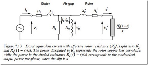
Of the power that is fed across the air-gap into the rotor, some is lost as heat in the rotor resistance, and the remainder (hopefully the majority!) is converted to useful mechanical output power. To represent this in the referred circuit we split the Wctitious resistance R 0 =s into two parts,
2 and R2( (1 – s)=s), as shown in Figure 7.13.
The rotor copper loss is represented by the power in R 0 , and the useful mechanical output power is represented by the power in the ‘electro- mechanical’ resistance R 0 ( (1 – s)=s), shown shaded in Figure 7.13. To further emphasise the intended function of the motor – the production of mechanical power – the electromechanical element is shown in Figure 7.13 as the secondary ‘load’ would be in a transformer. For the motor to be a good electromechanical energy converter, most of the power entering the circuit on the left must appear in the electromechanical load resistance. This is equivalent to saying that for good performance, the output voltage V 0 must be as near as possible to the input voltage, V1.
And if we ignore the current in the centre magnetising branch, the ‘good’ condition simply requires that the load resistance is large compared with the other series elements. This desirable condition is met under normal running condition, when the slip is small and hence R 0 ( (1 – s)=s) is large.
Our next step is to establish some important general formulae, and draw some broad conclusions.
and R0 ( (1 – s)=s). The power dissipated in R0 represents the rotor copper loss per-phase, while the power in the shaded resistance R0 ( (1 – s)=s) corresponds to the mechanical output power per-phase, when the slip is s
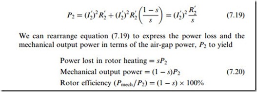
Power balance The power balance for the rotor can be derived as follows:
These relationships were mentioned in Chapters 5 and 6, and they are of fundamental importance and universal applicability. They show that of the power delivered across the air-gap fraction s is inevitably lost as heat, leaving the fraction (1 – s) as useful mechanical output. Hence an induction motor can only operate eYciently at low values of slip.
Torque
We can also obtain the relationship between the power entering the rotor and the torque developed. We know that mechanical power is torque times speed, and that when the slip is s the speed is (1 – s) vs, where vs is the synchronous speed. Hence from the power equations above we obtain
Again this is of fundamental importance, showing that the torque developed is proportional to the power entering the rotor.
All of the relationships derived in this section are universally applic- able and do not involve any approximations. Further useful deductions can be made when we simplify the equivalent circuit, but Wrst we will look at an example of performance prediction based on the exact circuit.


