CABLE DETAILS
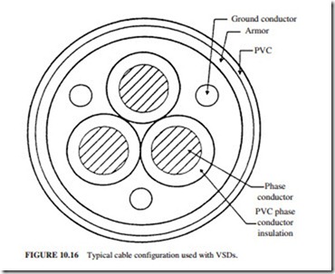
The continuous corrugated aluminum cable [NEC type MC (metal clad), Fig. 10.16] is best suited for PWM. It costs about 30 percent more than the “standard” variety with three conductors, one ground, and interlocked aluminum armor. Note the symmetry of the power and the ground conductors (only one random ground conductor is installed in most standard 60-
Hz power cables). The symmetry helps in canceling most of the stray fluxes. The symmetry in the cable also helps to reduce bearing currents and EMI (by providing better shielding).
Motor, Cable, and Power System Grounding
Proper termination of the cable is required to provide effective grounds and shielding for controlling the path of the currents. The proper termination must also be adequate for the life of the equipment (i.e., must not deteriorate due to corrosion). Good electrical and mechanical connections must be established at both ends of the cable between the contin- uous corrugated aluminum shield and the ground. The connection should provide low impedance for the high-frequency shield currents. The ground leads for the armor and cable should be properly terminated in the motor junction box. A machine tapered insert with internal threads should be used to terminate the armor. The contact between the shield and connector will be 360° (Figs. 10.17 and 10.18). The RC network from the center point of the inverter capacitor bank to ground provides good ac return for the cable shield currents and assists in limiting overcurrent transients during ground faults.
