Current Limit Control
The armature of a large DC motor has a very low resistance, typically less than 1 ohm. If the controller is turned on with full voltage applied to the armature, or if the motor stalls while full voltage is applied to the armature, a very large current will flow. This current can damage the armature of the motor or the electronic components of the controller. For this reason, most solid-state, DC motor controls use some method to limit the current to a safe value.
One method of sensing the current is to insert a low value of resistance in series with the armature circuit. The amount of voltage dropped across the sense resistor is proportional to the current flow through the resistor. When the voltage drop reaches a certain level, a signal is sent to the phase shift control telling it not to permit any more voltage to be applied to the armature.
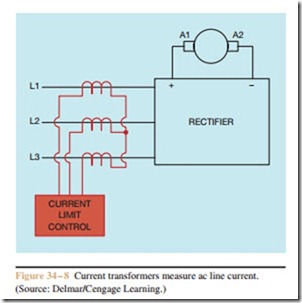
When DC motors of about 25 horsepower or larger are to be controlled, resistance connected in series with the armature can cause problems. Therefore, an- other method of sensing armature current can be used (Figure 34 – 8). In this circuit, current transformers are connected to the AC input lines. The current supplied to the rectifier will be proportional to the cur- rent supplied to the armature. When a predetermined
amount of current is detected by the current transformers, a signal is sent to the phase shift control telling it not to permit the voltage applied to the armature to increase (Figure 34 – 9). This method of sensing the armature current has the advantage of not adding resistance to the armature circuit. Regardless of the method used, the current limit control signals the phase shift control, and the phase shift control limits the voltage applied to the armature.
