Objectives
After studying this unit, the student will be able to:
• Discuss the operation of circuit #3
• Troubleshoot circuit #3 using the schematic
In this circuit, a float switch is used to oper ate a pump motor. The pump is used to fill a tank with water. When the tank is low on water, the float switch activates the pump motor and turns a red pilot light on. When the tank is filled with water, the float switch turns the pump motor and red pilot light off, and turns an amber pilot light on to indicate that the pump motor is not running. If the pump motor becomes overloaded, an over load relay stops the pump motor only.
The requirements for this circuit indicate that a float switch is to be used to control three differ ent items: a red pilot light, a motor starter, and an amber pilot light. However, most pilot devices, such as float switches, pressure switches, and limit switches, seldom contain more than two contacts. When the circuit requires these pilot devices to use more contacts than they contain, it is common practice to let a set of contacts on the pilot device operate a control relay. The contacts of the control relay can be used as needed to fulfill the require ments of the circuit.
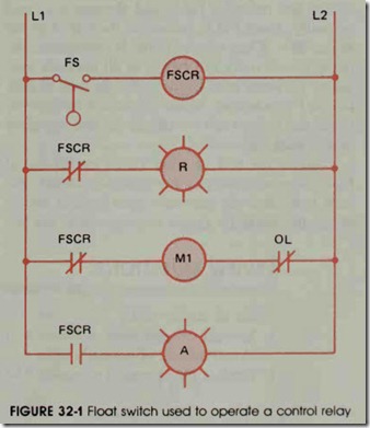
The float switch in figure 32-1 is used to op erate a control relay labeled FSCR. The contacts of the control relay are used to control the motor starter and the two pilot lights.
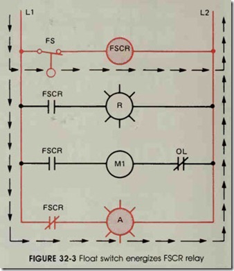
In the circuit shown in figure 32-2, current can flow through the normally closed FSCR con tact to the red pilot light, and through a second normally closed FSCR contact to the coil of motor starter Ml. When motor starter M1 energizes, the pump motor starts and begins to fill the tank with water. As water rises in the tank, the float of float switch FS rises also. When the tank is sufficiently filled, the float switch contact closes and energizes relay FSCR, figure 32-3.
When the coil of relay FSCR energizes, all FSCR contacts change. The normally closed con tacts open and the normally open contact closes. When the normally closed contacts open, the circuits to the red pilot light and to coil M1 are bro ken. When motor starter M1 de-energizes, the pump motor stops. When the normally open FSCR contact closes, current flows to the amber pilot light. When the pump motor turns off, the water level begins to drop in the tank. When the water level drops low enough, the float switch opens and de-energizes relay coil FSCR. When re lay FSCR de-energizes, all FSCR contacts return to their normal positions as shown in figure 32-1. If the pump motor is operating and the over load relay opens the overload contact, only the motor starter will be de-energized. The pilot lights will continue to operate.
REVIEW QUESTIONS
(Refer to circuit 32-1.)
1. Explain the operation of circuit 32-1 if float switch FS were connected normally closed instead of normally open.
2. Explain the operation of circuit 32-1 if relay coil M1 were burned out.


