Bidirectional trigger diodes
aBidirectional (two-directional) trigger diodes are used in TRIAC circuits because TRIACs have nonsym- metrical triggering characteristics; that is, they are not equally sensitive to gate current flowing in opposite directions. The most frequently used triggering device is the diAc (Diode AC).
The DIAC is constructed in the same manner as the transistor. It has three alternately doped layers (Figure 33-15). The only difference in the construction
is that the doping concentration around both junctions in the DIAC is equal. Leads are only attached to the outer layers. Because there are only two leads, the device is packaged like a P–N junction diode.
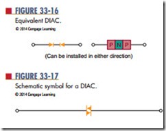
Both junctions are equally doped, so a DIAC has the same effect on current regardless of the direction of flow. One of the junctions is forward biased and the other is reverse biased. The reverse-biased junction controls the current flowing through the DIAC. The DIAC performs as if it contains two P–N junction diodes connected in series back to back (Figure 33-16). The DIAC remains in the off state until an applied voltage in either direction is high enough to cause its reverse-biased junction to break over and start conducting much like a zener diode. Break over is the point at which conduction starts to occur. This causes the DIAC to turn on and the current to rise to a value limited by a series resistor in the circuit.
The schematic symbol for a DIAC is shown in Fig- ure 33-17. It is similar to the symbol for a TRIAC. The difference is that a DIAC does not have a gate lead.
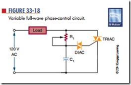
DIACs are most commonly used as a triggering device for TRIACs. Each time the DIAC turns on, it allows current to flow through the TRIAC gate, thus turning the TRIAC on. The DIAC is used in conjunction with the TRIAC to provide full-wave control of AC signals. Figure 33-18 shows a variable full-wave phase-control circuit. Variable resistor R1
and capacitor C1 form a phase-shift network. When the voltage across C1 reaches the breakover voltage of the DIAC, C1 partially discharges through the DIAC into the gate of the TRIAC. This discharge creates a pulse that triggers the TRIAC into conduction. This circuit is useful for controlling lamps, heaters, and speeds of small electrical motors.
1. Where are DIACs used in circuits?
2. Describe how a DIAC is constructed.
3. Explain how a DIAC works in a circuit.
4. Draw the schematic symbol for a DIAC.
Draw the schematic for a full-wave phase- control circuit using DIACs and TRIACs.


