Objectives
After studying this unit, the student will be able to:
• Describe the operation of a two-wire control circuit
• Describe the operation of a three-wire control circuit
TWO-WIRE CONTROLS
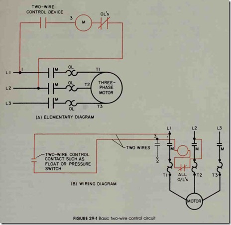
Magnetic control circuits are divided into two basic types: the two-wire control circuit, and the three-wire control circuit. Two-wire control cir cuits are operated by manual control devices such as the open starter in figure 12-1 or the manual push-button starter in figure 12-9B. This type of control circuit provides overload protection for the motor connected to it and provides under-voltage or no-voltage release. Figure 29-1 shows a typical two-wire control circuit. Notice that as long as the two-wire control device is closed, power can be supplied to the coil of the controller. If the motor is stopped by a power interruption, the two-wire control device will not open. Since the control de vice does not open, the motor will restart when power is restored to the system.
Two-wire control circuits are used in appli cations where this self restarting characteristic is desirable. This enables devices such as blower fans and pumps to restart after a power failure without an electrician having to walk around the plant and restart each device. Since two-wire control does permit automatic restarting of equipment, it could become a safety hazard to people working around the equipment. For this reason, two-wire controls should be used only when there is little or no dan ger of a person being injured if the equipment should suddenly restart after a power failure.
THREE-WIRE CONTROLS
Three-wire control circuits are generally op erated by momentary contact pilot devices. The simplest example of a three-wire control circuit is probably the start-stop, push-button control shown in figure 29-2. A set of auxiliary contacts controlled by M coil is connected parallel to the start button. These contacts are generally referred to as maintaining, sealing, or holding contacts. The job of this contact is to hold the coil in the circuit after the start button has been used to energize the relay.
If the start button in figure 29-2 is pressed, a circuit is completed between points 2 and 3, which allows current to flow through the motor starter coil and the normally closed overload contact to line 2 (L2). When current flows through the M relay coil, the relay energizes and closes all M con tacts. Since the contact that is connected parallel to the start button is now closed, the start button can be returned to its normally open position. Contact M maintains a current path around the start button to keep coil M energized.
Three-wire control is used to a much greater extent than two-wire control because of its flexi bility. Pilot devices such as push buttons can be located at remote locations such as control panels, while motor starters and control relays are housed in separate cabinets. Three-wire circuits also permit the use of different types of pilot devices such as float switches, pressure switches, and limit switches.
Since three-wire control circuits use holding contacts to maintain the circuit, if power is inter rupted, the equipment will not restart when power shown in figure 29-2 is stopped, M contacts will return to their normally open position. When power is restored, the start button must again be pressed to re-energize the M coil.
REVIEW QUESTIONS
1. What are some advantages of using two-wire control circuits?
2. What is a possible safety hazard of two-wire control circuits?
3. What is the advantage of a three-wire control system compared to a two-wire system?
4. What are holding contacts?

