INDUSTRIAL PHYSICAL SENSORS
Physical sensors measure the variations in physical properties of the samples, including temperature, moisture, density, thermal diffusivity, stiffness, thickness, bending stiffness, shear rigidity, elastic modulus, presence of irregularities (cracks, voids, and edges), defects, and strength etc. In theory, all measurable physical properties can be used in physical sensing applications, thus generating many possible physical sensors.
This section explains two kinds of physical sensors: temperature and distance sensors, which are important in industrial control systems.
Temperature sensors
Big differences exist between different temperature sensor or temperature measurement device types. Using one perspective, they can be simply classified into two groups, contact and noncontact.
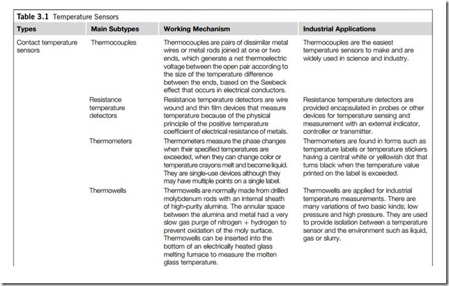
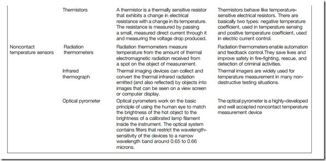
Contact temperature sensors measure their own temperature. The temperature of the object to which the sensor is in contact (is infered by assuming) that the two are in thermal equilibrium. Noncontact temperature sensors infer the temperature of an object by measuring the radiant power that is assumed to be emitted (some may be reflected rather than emitted). Table 3.1 lists some contact and noncontact temperature sensors.
The following paragraphs in this subsection introduce a contact temperature sensor: the bimetallic sensor.
(1) Operating principles of bimetallic sensors
Bimetallic sensors are electromechanical thermal sensors, or limiters, that are used for automatic temperature monitoring in industrial control. They limit the temperature of machines or devices by opening up the power load or electric circuit in the case of overheating, or by shutting off a ventilator or activating an alarm in the case of overcooling.
Bimetal sensors can also serve as time-delay devices. The usual technique is to pass current through a heater coil that eventually (after 10 seconds or so) warms the bimetal elements enough to actuate. This is the method employed on some controllers such as the cold-start fuel valves found on automobile engines.
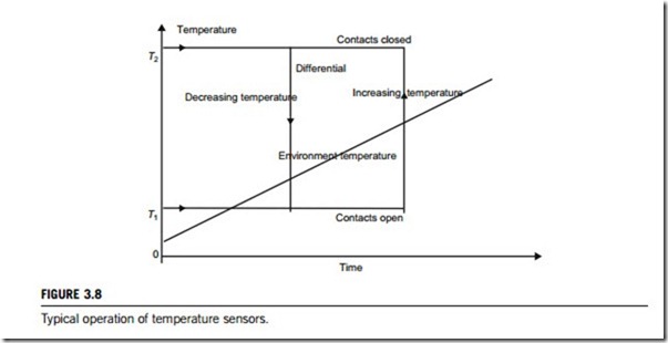
A bimetallic sensor essentially consists of two metal strips fixed together. If the two metals have different coefficients of thermal expansion, then as the temperature of the switch changes, one strip will expand more than the other, causing the device to bend out of plane. This mechanical bending can then be used to actuate an electromechanical switch or be part of an electrical circuit itself, so that contact of the bimetallic device with an electrode causes a circuit to be made. Figure 3.8 is a diagrammatic representation of the typical operation of temperature switches. There are two directional processes given in this diagram, which cause the contacts to change from open to closed and from closed to open, respectively:
(a) Event starts; the time is zero, the temperature of the sensor is T1, and the contacts are open. As the environment temperature increases, the sensor is abruptly heated and reaches the temperature T2 at some point, causing the contacts to close.
(b) When the temperature of the sensor is T2 and the contacts are closed, if the environment temperature keeps decreasing, the sensor is abruptly cooled, which takes the temperature to T1 at some point, causing the contacts to open again.
(2) Basic types of bimetallic sensors
Bimetallic sensors basically fall into two broad categories: creep action devices with slow make and slow break switching action; and snap action devices with quick make and quick break switching action.
Creep action devices are excellent either in temperature-control applications or as a high-limit controls. They have a narrow temperature differential between opening and closing, and generally have more rapid cycling characteristics than snap action devices.
Snap action devices are most often used for temperature-limiting applications, as their fairly wide differential between opening and closing temperature provides slower cycling characteristics.
Thermistors A thermistor is a thermally sensitive resistor that exhibits a change in electrical resistance with a change in its temperature.
The resistance is measured by passing
a small, measured direct current through it and measuring the voltage drop produced.
Thermistors behave like temperature- sensitive electrical resistors. There are basically two types: negative temperature coefficient, used in temperature sensing and positive temperature coefficient, used in electric current control.
Noncontact temperature sensors
Radiation thermometers
Infrared thermograph
Radiation thermometers measure temperature from the amount of thermal electromagnetic radiation received from a spot on the object of measurement.
Thermal imaging devices can collect and convert the thermal infrared radiation emitted (and also reflected) by objects into images that can be seen on a view screen or computer display.
Radiation thermometers enable automation and feedback control.They save lives and improve safety in fire-fighting, rescue, and detection of criminal activities.
Thermal imagers are widely used for temperature measurement in many non- destructive testing situations.
principle of using the human eye to match the brightness of the hot object to the brightness of a calibrated lamp filament inside the instrument. The optical system contains filters that restrict the wavelength- sensitivity of the devices to a narrow wavelength band around 0.65 to 0.66 microns.
The optical pyrometer is a highly-developed and well accepted noncontact temperature measurement device
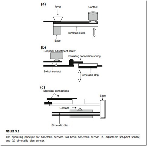
Although in its simplest form a bimetallic sensor can be constructed from two flat pieces of metal, in practical terms a whole range of shapes are used to provide maximum actuation or maximum force during thermal cycling. As shown in Figure 3.9, the bimetallic elements can be of three configurations in a bimetallic sensor:
(a) In Figure 3.9(a), two metals make up the bimetallic strip (hence the name). In this diagram, the black metal would be chosen to expand faster than the white metal if the device were being used in an oven, so that as the temperature rises the black metal expands faster. This causes the strip to bend downward, breaking contact so that current is cut off. In a refrigerator you would use the opposite set-up, so that as the temperature rises the white metal expands faster than the black metal. This causes the strip to bend upward, making contact so that current can flow. By adjusting the size of the gap between the strip and the contact, you can control the temperature.
(b) Another configuration uses a bimetallic element as a plunger, or pushrod, to force contacts open or closed. Here the bimetal does not twist or deflect, but instead is designed to lengthen or travel as a means of actuation, as illustrated by Figure 3.9(b). Bimetallic sensors can be designed to switch at a wide range of temperatures. The simplest devices have a single set-point temperature determined by the geometry of the bimetal and switch packaging. Examples include switches found in consumer products. More sophisticated devices for industrial use may incorporate calibration mechanisms for adjusting temperature sensitivity or switch-response times. These mechanisms typically use the separation between contacts as a means of changing the operating parameters.
(c) Bimetal elements can also be disk-shaped, as in Figure 3.9(c). These types often incorporate a dimple as a means of producing a snap action (not shown in this figure). Disk configurations tend to handle shock and vibration better than cantilevered bimetallic sensors.
Distance sensors
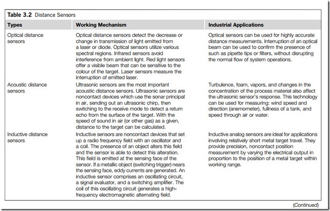
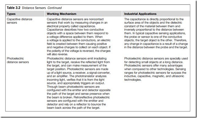
There are several kinds of distance sensors that work based on different physical mechanisms, including optical, acoustic, capacitive, inductive and photoelectric physics. These distance sensors can be classified into two groups; passive and active. A passive sensor does not emit, but just measures the change of a physical field around the sensor. In contrast, an active sensor not only emits but also measures the change of a physical field around the sensor.
Table 3.2 lists the main types of distance sensors. However, this subsection will focus on an active distance sensor; the ultrasonic distance sensor.
(1) Operating principles of ultrasonic sensors
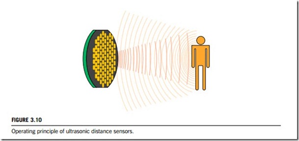
Ultrasonic distance sensors measure the distance to, or presence of target objects by sending a pulsed ultrasound wave at the object and then measuring the time for the sound echo to return. Knowing the speed of sound, the sensor can determine the distance of the target object.
As illustrated in Figure 3.10, the ultrasonic distance sensor regularly emits a barely audible click. It does this by briefly supplying a high voltage either to a piezoelectric crystal, or to the magnetic fields of ferromagnetic materials. In the first case, the crystal bends and sends out a sound wave. A timer within the sensor keeps track of exactly how long it takes the sound wave to bounce off a target and return. This delay is then converted into a voltage that corresponds to the distance from the sensed object.
In the second case, the physical response of a ferromagnetic material in a magnetic field is due to the presence of magnetic moments. Interaction of an external magnetic field with the domains causes a magnetostrictive effect. Controlling the ordering of the domains through alloy selection, thermal annealing, cold working, and magnetic field strength can optimize this effect. The magnetostrictive effects are produced by the use of magnetostrictive bars to control high-frequency oscillators and to produce ultrasonic waves in gases, liquids, and solids.
Applying converters based on the reversible piezoelectric effect makes one-head systems possible, where the converter serves both as transmitter and as receiver. The transceivers work by transmitting a short-burst ultrasonic packet. An internal clock starts simultaneously, measuring propagation time. The clock stops when the sound packet is received back at the sensor. The time elapsed between transmitting the packet and receiving the echo forms the basis for calculating distance. Complete control of the process is realized by an integrated microcontroller, which allows excellent output linearity.
(2) Basic types of ultrasonic sensors
The ultrasonic distance sensor can be operated in two different modes. The first mode, referred to as continuous (or analog) mode, involves the sensor continuously sending out sound waves at a rate determined by the manufacturer. The second mode, called clock (or digital) mode, involves the sensor sending out signals at a rate determined by the user. This rate can be several signals per second with the use of a timing device, or it can be triggered intermittently by an event such as the press of a button.
The major benefit of ultrasonic distance sensors is their ability to measure difficult targets; solids, liquids, powders, and even transparent and highly reflective materials that would cause problems for optical sensors. In addition, analog output ultrasonic sensors offer comparatively long ranges, in many cases > 3 m. They can also be very small some tubular models are only 12 mm in diameter, and 15 mm X 20 mm X 49 mm square-bodied versions are available for limited-space applications.
Ultrasonic devices do have some limitations. Foam, or other attenuating surfaces may absorb most
of the sound, significantly decreasing the measuring range. Extremely rough surfaces may diffuse the sound excessively, decreasing range and resolution. However, an optimal resolution is usually guar- anteed up to a surface roughness of 0.2 mm. Ultrasonic sensors emit a wide sonic cone, limiting their usefulness for small target measurement and increasing the chance of receiving feedback from interfering objects. Some ultrasonic devices offer a sonic cone angle as narrow as 6 degrees, permitting
detection of very small objects, and sensing of targets through narrow spaces such as bottlenecks, pipes, and ampoules.
