Polyphase Motors
Three-phase motors offer extremely efficient and economical application and are usually the preferred type for commercial and industrial applica tions when three-phase service is available. These motors are available in ratings from fractional hp up to thousands of hp in practically every stan dard voltage and frequency. In fact, there are few applications in which the three-phase motor cannot be put to use.
Three-phase motors are noted for their relatively constant-speed characteristic and are available in designs giving a variety of torque char acteristics; that is, some have a high starting torque while others a low starting torque. Some are designed to draw a normal starting current and others, a high starting current.
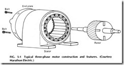
A typical three-phase motor is shown in Fig. 5-1. Note that the three main parts are the stator, rotor, and end plates. It is very similar in con struction to conventional split-phase motors except that the three-phase motor has no centrifugal switch.
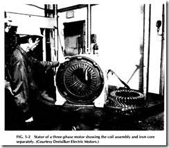
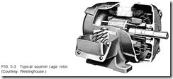
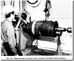
The stator shown in Fig. 5-2 consists of a steel frame and a lami nated iron core and a winding formed of individual coils placed in slots. The rotor may be a squirrel cage or wound rotor type. Both types contain a laminated core pressed onto a shaft. The squirrel cage rotor is shown in Fig. 5-3 and is similar to a split-phase motor. The wound rotor is shown in Fig. 5-4 and has a winding on the core that is connected to slip rings mounted on the shaft.
The end plates or brackets are bolted to each side of the stator frame and contain the bearings in which the shaft revolves. Either ball bearings or sleeve bearings are used.
OPERATING PRINCIPLES OF TWO-PHASE MOTORS
Two-phase motors are designed to operate on two-phase alternating cur rent and have two windings, each covering one half of each pole, or spaced 90 o apart, similar to the starting and running windings of a single-phase motor.
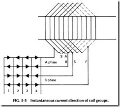
Each of the windings in a two-phase motor, however, is of the same size wire and has the same number of turns. Instead of being wound with spiral coils, two-phase windings are generally made with diamond-shaped coils similar to those used in armatures. A section of a two-phase winding is shown in Fig. 5-5. Note the manner in which the three coils of each phase overlap in forming the winding for one pole of the motor.
In Fig. 5-6 are shown the curves for two-phase current with alterna tions 90° apart. When the current flows through the two windings, it sets up poles that progress step by step around the stator so rapidly that it produces what is practically a revolving magnetic field. The progress of this field and the magnetic poles can be observed by tracing out and com paring the illustration in Fig. 5-7 to the one in Fig. 5-6. The dashed lines running vertically through the curves in Fig. 5-6 indicate the polarity of the curves at that instant and are referred to as positions.
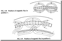
In position 1of Fig. 5-6, A and B are both positive, and, referring to position 1 at the leads of the windings in Fig. 5-5, current will flow in the starting leads of the two windings marked S and S. The polarity set up will be as shown by the positive and negative marks in Fig. 5-7 at posi tion 1. At this instant, the current flows in at all six wires on the left (Fig. 5-5) and out at all six wires on the right. See Fig. 5-7, bottom line. This will set up a magnetic flux or polarity as shown in the sketch of the mag netic circuit, position 1, shown in Fig. 5-8, showing that the center of the pole at this instant will be in the exact center of the coils and that a north pole will be produced at this point on the stator teeth.
At position 2 in Fig. 5-6, the B phase is still positive, but the A phase has changed to negative. Therefore, the current in the starting lead of the A phase will reverse as shown at position 2 and cause a reversal of polarity around the A group. As this group covers the first half of the pole, these three slots will change in polarity. The first three slots of the second pole will also change and cause the pole to move three slots to the right as shown in position 2 in Fig. 5-7. This shift of the magnetic pole is also illustrated in the magnetic sketch in Fig. 5-9.
At position 3 in Fig. 5-6, B has changed to negative, and the current in the leads of the B phase (Fig. 5-5) will reverse, causing the last three slots in each pole to change in polarity so the center of the pole moves three more slots to the right, as shown in Fig. 5-7.
The currents in the coil groups reverse in the manner just described and keep shifting the magnetic poles to the right; a corresponding change or movement of the field takes place in the stator. As this flux moves to the right and cuts across the rotor bars, it induces currents in them, and the reaction between the poles of this secondary current in the rotor and the stator poles causes the field of the stator poles to be distorted from its natural shape. It is from this distortion that the torque or twisting force is produced and causes the rotor to turn.
OPERATING PRINCIPLES OF THREE-PHASE MOTORS
The rotating action of the field in a three-phase motor is very much the same as that of two-phase motors, with the exception that only one third of the pole, or two slots, reverses at a time. In the two-phase motor, one half of the pole, or three slots, changes at each reversal of current. The coil groups of the three-phase winding should be placed in the slots in such a manner that they alternate in the same order as the currents change in the three-phase system.
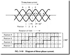
Observe the three-phase current curves in Fig. 5-10 and note that the alternations change polarity or cross the center line in the order A, C, B, etc. The coil groups should be wound in to correspond with these cur rent changes, or in the order A, C, B, etc.
At any given time in three-phase systems, the voltage or current curves above the zero line will exactly equal those below the line as can be seen in Fig. 5-10.
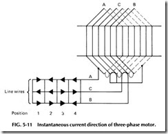
There is another condition that always exists in three-phase wind ings. Trace the current in toward the winding on the line wires in Fig. 5-11 and note that the center group, or C phase, will be traced around the coils in the direction opposite to the A and B phases. Keep in mind that the three currents never flow toward the winding at the same time and that there will always be a return current on one of the wires. Therefore, at any time when all three wires are carrying current, there will either be two positives and one negative or two negatives and one positive.
When these three currents flow through a three-phase winding, three consecutive coil groups will be of the same polarity, and the next three groups will be of opposite polarity, building up alternate poles; that is, N.S., N.S., etc. From this, it should be seen how the field poles pro gress around the stator to produce a revolving magnetic field in a three phase motor.
Trace out and compare each of the positions (1, 2, 3, and 4) in Fig. 5-10 and compare them to the diagram in Fig. 5-11; note the manner in which the field poles gradually advance in the slots as the current alter nates in the three phases, A, C, and B.
POLYPHASE MOTOR ENCLOSURES
Polyphase induction motors differ in construction and appearance, de pending on the type of service for which they are to be used. Open and closed frames are quite common. In the former enclosure, the motor’s parts are covered for protection, but the air can freely enter the enclosure. Further designations for this type of enclosure include drip-proof, weather protected, and splash-proof.
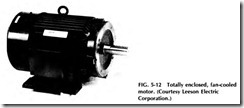
Totally enclosed motors, such as the one shown in Fig. 5-12, have an airtight enclosure. They may be fan-cooled or self-ventilated. An enclosed motor equipped with a fan (Fig. 5-12) has the fan as an integral part of the machine but external to the enclosed parts. In the self-ventilated enclosure, no external means of cooling is provided.
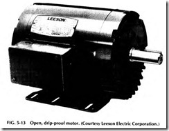
The type of enclosure used will depend on the ambient and surround ing conditions. In a drip-proof machine (see Fig. 5-13), for example, all ventilating openings are so constructed that drops of liquid or solid par ticles falling on the machine at an angle of not greater than 15o from the vertical cannot enter the machine, even directly or by striking and run ning along a horizontal or inclined surface of the machine. The applica tion of this machine would lend itself to areas where liquids are processed.
An open motor having all air openings which give direct access to live or rotating parts, other than the shaft, limited in size by the design of the parts or by screen to prevent accidental contact with such parts is classified as a drip-proof, fully guarded machine. In such enclosures, openings shall not permit the passage of a cylindrical rod Y2 in. in diam eter, except where the distance from the guard to the live rotating parts is more than 4 in., in which case the openings shall not permit the passage of a cylindrical rod 314 in. in diameter. See Fig. 5-14.
There are other special applications of drip-proof machines, such as externally ventilated and pipe ventilated, which, as the names imply, are either ventilated by a separate motor-driven blower or cooled by ventilat ing air from inlet ducts or pipes.
An enclosed motor whose enclosure is designed and constructed to withstand an explosion of a specified gas or vapor which may occur within the motor and to prevent the ignition of this gas or vapor sur rounding the machine is designated an explosion-proof(XP) motor.
Hazardous atmospheres (requiring XP enclosures) of both a gaseous and dusty nature are classified by the NE Code as follows:
Class I, Group A: atmospheres containing acetylene Class I, Group B: atmospheres containing hydrogen or gases or vapors of equivalent hazards such as manufactured gas
Class I, Group C: atmospheres containing ethylether vapor
Class I, Group D: atmospheres containing gasoline, petroleum,
naphtha, alcohols, acetone, lacquer-solvent vapors, and natural gas
Class II, GroupE: atmospheres containing metal dust
Class II, Group F: atmospheres containing carbon-black, coal, or coke dust
Class II, Group G: atmospheres containing grain dust
The proper motor enclosure must be selected to fit the particular atmospheres. However, explosion-proof equipment is not generally avail able for class I, groups A and B, and it is therefore necessary to isolate motors from the hazardous area.
