INTRODUCTION
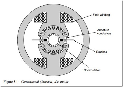
Until the 1980s the conventional (brushed) d.c. machine was the auto- matic choice where speed or torque control is called for, and large numbers remain in service despite a declining market share that reXects the move to inverter-fed induction motors. Applications range from steel rolling mills, railway traction, to a very wide range of industrial drives, robotics, printers, and precision servos. The range of power outputs is correspondingly wide, from several megawatts at the top end down to only a few watts, but except for a few of the small low-performance ones, such as those used in toys, all have the same basic structure, as shown in Figure 3.1.
The motor has two separate circuits. The smaller pair of terminals connect to the Weld windings, which surround each pole and are normally in series: in the steady state all the input power to the Weld windings is dissipated as heat – none of it is converted to mechanical output power. The main terminals convey the ‘power’ or ‘work’ current to the brushes which make sliding contact to the armature winding on the rotor. The supply to the Weld is separate from that for the armature, hence the description ‘separately excited’.
As in any electrical machine it is possible to design a d.c. motor for any desired supply voltage, but for several reasons it is unusual to Wnd rated voltages lower than about 6 V or much higher than 700 V. The lower limit arises because the brushes (see below) give rise to an un- avoidable volt-drop of perhaps 0.5–1 V, and it is clearly not good practice to let this ‘wasted’ voltage became a large fraction of the supply voltage. At the other end of the scale, it becomes prohibitively expensive to insulate the commutator segments to withstand higher voltages. The function and operation of the commutator is discussed later, but it is appropriate to mention here that brushes and commutators are
troublesome at very high speeds. Small d.c. motors, say up to hundreds of watts output, can run at perhaps 12 000 rev/min, but the majority of medium and large motors are usually designed for speeds below 3000 rev/min.
Increasingly, motors are being supplied with power-electronic drives, which draw power from the a.c. mains and convert it to d.c. for the motor. Since the mains voltages tend to be standardised (e.g. 110 V, 220–240 V, or 380– 440 V, 50 or 60 Hz), motors are made with rated voltages which match the range of d.c. outputs from the converter (see Chapter 2).
As mentioned above, it is quite normal for a motor of a given power, speed and size to be available in a range of diVerent voltages. In principle, all that has to be done is to alter the number of turns and the size of wire making up the coils in the machine. A 12 V, 4 A motor, for example, could easily be made to operate from 24 V instead, by winding its coils with twice as many turns of wire having only half the cross-sectional area of the original. The full speed would be the same at 24 V as the original was at 12 V, and the rated current would be 2 A, rather than 4 A. The input power and output power would be un- changed, and externally there would be no change in appearance, except that the terminals might be a bit smaller.
Traditionally d.c. motors were classiWed as shunt, series or separately
excited. In addition it was common to see motors referred to as ‘compound-wound’. These descriptions date from the period before the advent of power electronics, and a strong association built up, linking one or other ‘type’ of d.c. machine with a particular application. There is really no fundamental diVerence between shunt, series or separately excited machines, and the names simply reXect the way in which the Weld and armature circuits are interconnected. The terms still persist, however, and we will refer to them again later. But Wrst we must gain an understanding of how the basic machine operates, so that we are equipped to understand what the various historic terms mean, and hence see how modern practice is deployed to achieve the same ends.
We should make clear at this point that whereas in an a.c. machine the number of poles is of prime importance in determining the speed, the pole number in a d.c. machine is of little consequence as far as the user is concerned. It turns out to be more economical to use two or four poles in small or medium size d.c. motors, and more (e.g. ten or twelve or even more) in large ones, but the only diVerence to the user is that the 2-pole type will have two brushes at 1808, the 4-pole will have four brushes at 908, and so on. Most of our discussion centres on the 2-pole version in the interests of simplicity, but there is no essential diVerence as far as operating characteristics are concerned.
