Equivalent Circuit
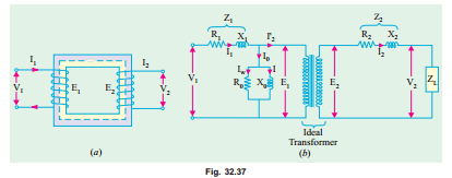
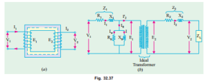
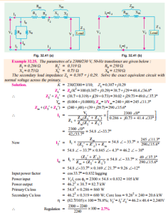
The transformer shown diagrammatically in Fig. 32.37 (a) can be resolved into an equivalent circuit in which the resistance and leakage reactance of the transformer are imagined to be external to the winding whose only function then is to transform the voltage (Fig. 32.37 (b)). The no-load
current I0 is simulated by pure inductance X 0 taking the magnetising component Iµ and a non-inductive resistance R0 taking the working component Iw connected in parallel across the primary circuit. The value of E1 is obtained by subtracting vectorially I1 Z1 fromV 1. The value of X 0 = E1/I0 and of R0 = E1/Iw. It is clear that E1 and E2 are related to each other by expression
E2/E1 = N2/N1 = K.
To make transformer calculations simpler, it is preferable to transfer voltage, current and impedance either to the primary or to the secondary. In that case, we would have to work in one winding only which is more convenient.
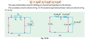
The primary equivalent of the secondary induced voltage is E2¢ = E2/K = E1. Similarly, primary equivalent of secondary terminal or output voltage is V2¢ = V2/K. Primary equivalent of the secondary current is I2¢ = KI2.
For transferring secondary impedance to primary K2 is used.
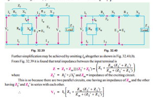
The total equivalent circuit of the transformer is obtained by adding in the primary impedance as shown in Fig. 32.39. This is known as the exact equivalent circuit but it presents a somewhat harder circuit problem to solve. A simplification can be made by transferring the exciting circuit across the terminals as in Fig. 32.40 or in Fig. 32.41 (a). It should be noted that in this case X 0 = V 1/Iµ.
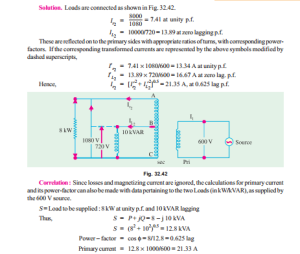
Example 32.26. A transformer has a primary winding with a voltage-rating of 600 V. Its secondary-voltage rating is 1080 V with an additional tap at 720 V. An 8 kW resistive load is connected across 1080-V output terminals. A purely inductive load of 10kVA is connected across the tapping point and common secondary terminal so as to get 720 V. Calculate the primary current and its power-factor. Correlate it with the existing secondary loads. Neglect losses and magnetizing current.
(Nagpur University, Winter 1999)
Transformer Tests
As shown in Ex 32.25, the performance of a transformer can be calculated on the basis of its equivalent circuit which contains (Fig. 32.41) four main parameters, the equivalent resistance R01 as referred to primary (or secondary R02), the equivalent leakage reactance X 01 as referred to primary (or secondary X 02), the core-loss conductance G0 (or resistance R0) and the magnetising susceptance B0 (or reactance X0). These constants or parameters can be easily determined by two tests (i) open-circuit test and (ii) short circuit test. These tests are very economical and convenient, because they furnish the required information without actually loading the transformer. In fact, the testing of very large a.c. machinery consists of running two tests similar to the open and short-circuit tests of a transformer.
Related posts:
Incoming search terms:
- transformer equivalent circuit problems
- equivalent circuit of transformer problem
- how to solve transformer equivalent circuit problems
- image of transformer equivalent circuit
- transformer equivalent circuit solved problems
- equivalent circuit of transformer problems
- equivalent circuit of two transformers in parallel image
