GENERAL MOTORS EFE
Early Fuel Evaporation Valve Controlled
This system is used on 1975-76 vehicles to provide a source of rapid heat for quick induction system warm-up during cold engine operation. Rapid heat is more desirable because it provides for better fuel evaporation and a more uniform mixture.
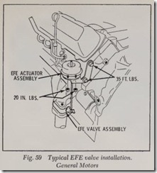
The vacuum operated EFE heat control valve mounted between the exhaust manifold and pipe, Fig. 59, directs a portion of the exhaust gasses through the intake manifold and to the base of the carburetor during engine warm-up. A thermal vacuum switch ( TVS) is used to regulate the EFE valve at or below a predetermined temperature. Refer to chart.
VS-454
1975 …………………..100° F.
1976 …………………..150°F.
Oldsmobile ……………….120° F.
When engine coolant (oil on 6-250) is at or be low the specified temperature, the TVS will cause vacuum to flow to the EFE control valve, diverting the exhaust gasses through the intake manifold to the base of the carburetor. At temperatures above those specified, the TVS closes off vacuum to the EFE control valve, stopping the flow of exhaust gasses through the intake manifold.Pontiac …………………..150° F.
Orifice Controlled
The orifice controlled EFE system is used on some 1977 Pontiac models. This system consists of an orifice restriction in one end of the exhaust crossover pipe which increases the flow of exhaust gases through the exhaust crossover under the in take manifold. This type of EFE is in effect when ever the engine is running.
CHRYSLER LEAN BURN ENGINE ELECTRONIC SPARK ADVANCE
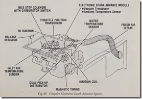
This system, Fig. 60, used on some 1976-77 en gines, allows the engine to run at an air/fuel ratio of 18 to 1. Since the engine runs lean, NOx, HC and CO emissions are reduced without the use of EGR, OSAC, air pumps, catalytic converters, vacuum advance units, some special heat shields and all interconnecting hoses. However, for California applications, the use of catalytic converters and heat shields is retained.
Six sensors are mounted on the engine which monitor the following operating conditions:
1. Engine condition when started (Hot or cold start).
2. Engine RPM and piston position in relation to TDC.
3. Intake manifold vacuum.
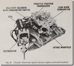
4. Throttle position, Fig. 61.
5. Rate of change in throttle position.
6. Carburetor air temperature.
7. Coolant temperature.
The information from the sensors is sent to the spark control computer which calculates the pre cise instant the fuel charge should be fired in each cylinder to provide the best combination of drive ability, fuel economy and emission control.
The computer, which is the brain of the elec tronic spark advance system, sends signals for each cylinder to the electronic distributor. The dis tributor, in turn, controls the firing of the spark plugs. The distributor incorporates two magnetic pick-ups. One pick-up is used during engine start and operation for sixty seconds after which the second pick-up is activated and the “Start” pick-up is deactivated, regardless of operating condi tions. Also, the system incorporates a “Limp-In” mode whereby, if ignition failure occurs, vehicle can still be driven into a service station.
CHRYSLER CAP
Cleaner Air Package
The Cleaner Air Package is in addition to the Positive Crankcase Ventilation ( PCV). The PCV device is designed to conh·ol the emission of hydrocarbon vapors from the crankcase, whereas the Cleaner Air Package controls the emission of hydrocarbon vapors (unburned gasoline) and carbon monoxide in the vehicle exhaust.
The Cleaner Air Package is engineered to continuously control carburetion and ignition at the best settings for perfonnance and combustion during all driving conditions. These adjustments keep unburned gasoline and carbon monoxide in the exhaust at a minimum concentration.
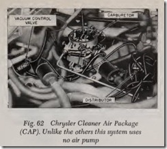
Only three special components are involved inthe CAP installation, Fig. 62. The carburetor and distributor have been re-designed and a new component-the Vacuum Advance Control Valve
-has been added. In addition, some cooling sys tem components have been changed to handle the increased heat rejection at idle and low speed.
Special Carburetor and Ignition
The carburetor is specially calibrated to provide leaner mixtures at idle and low speed operation. The distributor is designed to give retarded timing at idle. The vacuum advance control valve, in conjunction with the distributor, provides ad vanced timing during deceleration.
CAP idle timing for all engines is retarded in stead of advanced. Exhaust emission is reduced at idle by using leaner air/fuel mixtures, increased engine speed, and retarded ignition timing. The higher air flow at this idle condition approximates the desirable conditions of cruise. CAP, therefore, is designed to operate with late timing during idle, and with conventional spark advance during ac celeration and cruise.
Vacuum Advance Control Valve, 1967-68 All; 1969 6-170 with Std. Trans. & 1969 VS-426 Hemi
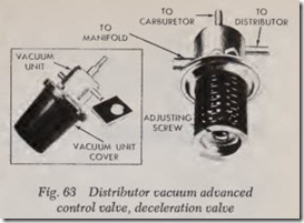
Early ignition of the airjfuel mixture is needed during deceleration to provide the most efficient combustion and reduced exhaust emissions. The vacuum advance control valve provides that addi tional spark advance during deceleration. The vacuum advance control valve is connected by vacuum hoses to the carburetor, to the intake manifold, and to the distributor vacuum chamber, Fig. 63.
Carburetor vacuum and manifold vacuum act on the vacuum advance control valve. From these two signals, the vacuum advance control valve senses engine speed and load conditions, and re lays a vacuum signal to the distributor to vary spark timing when necessary to reduce emissions to an acceptable level.
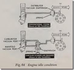
Engine Idle, Fig. 64
The initial idle timing is retarded as much as 15 degrees from conventional timing. The vacuum advance control valve does not affect timing at idle because the distributor vacuum chamber receives the same vacuum signal as in the conventional system, namely, carburetor vacuum. At idle it is not strong enough to overcome the distributor vacuum diaphragm spring.
Manifold vacuum acts on the vacuum control valve diaphragm, but is not strong enough to overcome the vacuum control valve spring. So the spring holds the vacuum control valve closed to manifold vacuum and opens the low carburetor vacuum.
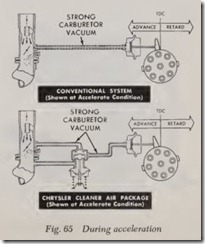
Acceleration, Fig. 65
During acceleration and cruise, manifold vacuum is not strong enough to actuate the CAP control valve. Thus the CAP system operates in the same manner as the conventional system. The throttle blade opens enough to permit the dis tributor vacuum advance to function, and spark timing is advanced according to the amount of vacuum created by the pumping action of the pistons.
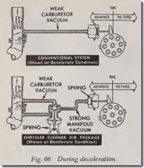
Deceleration, Fig. 66
The conventional system provides the highest emissions under d!’)celeration conditions. Carbure tor vacuum is too weak to overcome the distributor advance diaphragm spring.
Manifold vacuum is at its strongest under de celeration conditions. Therefore , the CAP system uses manifold vacuum rather than carburetor vac· uum to control spark timing.
Manifold vacuum is strong enough to overcome the vacuum advance control valve spring and the distributor vacuum diaphragm spring, moving spark timing to the maximum advance condition.
CHRYSLER CAS
Cleaner Air System
This system uses higher inlet air temperature,higher idle speeds, retarded ignition timing, leaner carburetor mixtures and built in modifications such as lower compression ratios, increased overlap camshafts and redesigned intake manifolds and combustion chambers.
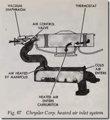
Heated Air System, Fig. 67
This system uses a thermostatically controlled air cleaner to maintain a pre-determined air tem perature entering the carburetor when underhood temperatures are less than 100° F. By maintaining this temperature, the carburetor can be calibrated leaner, improve engine warm-up and minimize carburetor icing. Temperature is controlled by intake manifold vacuum, a temperature sensor and a vacuum diaphragm which operates the heat con trol door in the air cleaner snorkel.
During engine warm-up, air is heated by a shroud surrounding the exhaust manifold, then the air is piped to the air cleaner snorkel and into the carburetor. The vacuum diaphragm controls the air control valve which is closed to outside air. Therefore all air entering the carburetor is heated.
During normal operation, as the air entering the air cleaner increases, the air control valve opens to allow heated air to mix with cold air to keep the air entering the carburetor at about 100° F.
During wide-open throttle operation or at any time engine vacuum is below 4-6 inches Hg., the hot air duct is closed off allowing only cold air to e ter the carburetor.
Dual Snorkel
The dual snorkel air cleaner performs at low temperature and above 105 deg. F. basically like a single snorkel air cleaner except that on deep throttle acceleration, both snorkels are open (when manifold vacuum drops between 5″ Hg) .
The “non-heat” air snorkel is connected to manifold vacuum through a tee in the vacuum hose between the carburetor and the sensor.
Lower Compression Ratios
Compression ratios have been lowered by vari ous modifications in the piston head design and in the quench height. This reduction in compression ratios permits the engine to operate satisfactorily on lower octane fuel, thereby achieving a slight re duction in HC and NOx emission levels.
Combustion Chamber Design
The combustion chamber is designed to elimi-nate pockets and close clearance spaces which have a tendency to quench the flame before all of the air-fuel mixture is burned. By increasing the quench heights, more complete burning of the air fuel mixture is achieved, thereby substantially re ducing the HC emission levels.
Increased Overlap Camshaft
The increased valve overlap produced by the camshaft causes some dilution of the incoming air fuel mixture. This dilution lowers the peak com bustion temperature which results in lowered NOx emission levels.
Redesigned Intake Manifold
Intake manifolds have been redesigned to pro mote rapid fuel vaporization during engine warm up. The exhaust crossover floor of the intake mani fold between the inlet gases and exhaust gases has been thinned out with improved thickness control, thereby reducing the time required to get the heat from the exhaust manifold gases into the inlet gases. By adding this additional heat, fuel vapor izes quicker, and leaner air-fuel mixtures can be used, resulting in lower CO emission levels.
Idle Speed Solenoid
Because of the high idle speeds used on some high performance engines, these engines have an electrical solenoid throttle stop which holds the throttle at the correct idle position when energized but de-energizes when the ignition is turned off, allowing the throttle blades to close more completely, thereby eliminating the possibility of “after-run” or “dieseling.”
Distributor Solenoid
Some engines have a solenoid incorporated in the distributor vacuum advance mechanism to re tard the ignition timing when the throttle is closed. At closed throttle, and with the idle adjusting screw in the closed position, electrical contacts on the carburetor throttle stop cause the distribu tor solenoid to energize. This retards the ignition timing to reduce emissions dming hot idle condi tions. Cold or part throttle starting is not penalized because the distributor solenoid is not energized unless the hot idle adjusting screw is against the throttle stop contact.
NOTE: Ignition timing must be set at closed throttle to give accurate setting.

