Short-Circuit or Impedance Test
This is an economical method for determining the following :
(i) Equivalent impedance (Z01 or Z02), leakage reactance (X 01 or X 02) and total resistance (R01 or R02) of the transformer as referred to the winding in which the measuring instruments are placed.
(ii) Cu loss at full load (and at any de- sired load). This loss is used in calculating the efficiency of the transformer.
(iii) Knowing Z01 or Z02, the total voltage drop in the transformer as referred to primary or secondary can be calculated and hence regulation of the transformer determined.
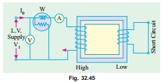
In this test, one winding, usually the low-voltage winding, is solidly short-circuited by a thick conductor (or through an ammeter which may serve the additional purpose of indicating rated load current) as shown in Fig. 32.45.

A low voltage (usually 5 to 10% of normal primary voltage) at correct frequency (though for Cu losses it is not essential) is applied to the primary and is cautiously increased till full-load currents are flowing both in primary and secondary (as indicated by the respective ammeters).
Since, in this test, the applied voltage is a small percentage of the normal voltage, the mutual flux F produced is also a small percentage of its normal value (Art. 32.6). Hence, core losses are very small with the result that the wattmeter reading represent the full-load Cu loss or I2R loss for the whole transformer i.e. both primary Cu loss and secondary Cu loss. The equivalent circuit of the transformer under short-circuit condition is shown in Fig. 32.46. If Vsc is the voltage required to circulate rated load currents, then
