TYPICAL GENERATOR OPERATIONAL PROBLEMS
The typical operational problems encountered with generator rotors are
● Shorted turns
● Field grounds
● Thermal sensitivity
● Negative sequence heating
● Contamination
● Misoperation
● Forging damage
Shorted Turns and Field Grounds
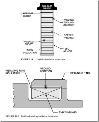
A shorted turn fault (known also as a winding short or an interturn fault) occurs due to failure of the insulation between the winding turns of the rotor. These faults are not desirable. However, rotors have operated with a limited number of short turns without suffering significant effects on generator operation. Shorts can occur anywhere in the rotor winding. However, they are frequently located in the end windings under the retaining rings.
Ground faults are caused by the failure of the ground wall insulation. The generator should not be operated following a grounded fault in the rotor. A single ground fault will not cause a circulating current in the forging (the rotor body) because the source of excitation is ungrounded. However, if a second ground fault occurs, the current will circulate in the forging, causing melting and serious damage to the rotor insulation.
Figure 18.1 illustrates a winding short and a ground fault in the slot of a generator rotor. Figure 18.2 illustrates a ground fault in the end winding between the top turn of the winding and the retaining ring.
The following conditions can cause breakdown in the rotor insulation:
Operation Time. During normal operation, the insulation is exposed to electrical, mechanical, and thermal stresses. Thus, the condition of the insulation is expected to degrade with operation time.
Type of Operation. The condition of the insulation degrades faster in a generator that experiences frequent shutdowns or frequent cycling in the field current (to change the amount of reactive power delivered from the generator) than in a generator that operates at base load.
Contamination. The condition of the insulation degrades due to the presence of contamination or burning inside the generator (burning produces conductive material that circu- lates throughout the generator).
Abnormal Operating Incidents. The rotor insulation deteriorates following an abnormal incident that results in heating, burning, arcing, high stress, etc. These incidents include generator motoring (i.e., the generator acts as a motor when it is synchronized to the grid and there is no steam or hot gas driving the turbine), a negative sequence event (unbalance in the three phases in the stator, which can be caused by closing the generator breaker when the voltage in the three phases is different from the corresponding voltages in the grid), burning inside the generator, or an overspeed incident.
As mentioned earlier, the generator can operate satisfactorily with interturn faults (shorted turns) in the rotor windings. However, the generator should not be operated with a ground fault.
Shorted turns do not subject the machine to high risk. The consequences of operating a rotor with shorted turns include the following:
1. Inability to reach the nominal rating of the machine
2. Possibility of developing an unbalance in the rotor that will result in high vibrations
In the worst case, a complete rewind of the rotor will be required.
When one ground fault occurs, the current will not flow in the forging (body of the rotor). However, when a second ground fault occurs, the current will start to flow between the two ground points. The resulting heat generation (from the current) could melt the forging within a few seconds.
The cause of the ground fault should be investigated immediately and corrective action taken. Operation with one ground fault could lead to serious damage, should a second ground fault occur.
Shorted turns will develop in the rotor after a long period of operation. Many generators have operated satisfactorily for years with shorted turns. The shorted turns should be repaired only when continued generator operation becomes unacceptable due to unit derating or high vibrations. The generator field should be inspected and tested regularly to con- firm the integrity of the insulation system. Diagnostic tests can identify the location of an insulation fault and its severity. This ability for taking quick corrective action allows the rotor to be returned to service within a short time.
The following additional concerns affect rotor operation.
Thermal Sensitivity
The excessive rotor vibration caused by the heating effect resulting from an interturn fault is known as thermal sensitivity. The rotor tends to bow due to the temperature differential across it. This leads to imbalance and high vibrations.
The following factors can cause thermal sensitivity:
Shorted Turns. The windings of a pole having several shorted turns will have lower resistance than the windings of a healthy pole. Since the current flowing in the poles is the same, the pole having a higher winding resistance (healthy pole) will heat up and expand more than the other. This causes a rotor bow in the direction of the healthy pole.
Blocked Ventilation. The rotor will have uneven temperature distribution if a ventilation path becomes blocked. This will lead to a rotor bow similar to the one caused by short turns.
Uneven Insulation. Nonuniform field insulation can cause the field coils to bind in the slots and in the end windings (under the retaining ring). This will lead to transmitting uneven axial forces on the rotor, causing it to bow.
Uneven Wedge Tightness. Uneven tightness of the wedges can cause nonuniform axial force distribution around the rotor. This will also lead to a bow in the rotor.
Uneven End Winding Insulation. Unevenly spaced and fitted end winding insulation can cause nonuniform forces to be transmitted to the rotor. This will also cause bowing in the rotor, leading to high vibrations.
There are two types of thermal sensitivity: reversible and irreversible. The reversible type is characterized by a repeatable behavior. In this case, the rotor vibration varies lin- early with the field current. The thermal sensitivity is considered irreversible, or slipstick, if the rotor vibrations increase with the field current and do not decrease when the current drops. The type of thermal sensitivity should be identified by performing tests. This will aid in determining the corrective action required to eliminate the problem.
Contamination
The cooling method of the generator determines the type and extent of contamination found in it. A hydrogen-cooled generator normally has little contamination because it is well sealed. A totally enclosed water to air cooled (TEWAC) unit will have some particles due to makeup air. An open ventilated (OV) generator will have large amounts of contamination in it.
Carbon is a common contaminant in generators. It originates from slip ring (collector) brush wear or the exhaust of gas turbines. Silicon or petroleum by-products are also found in some generators. They originate from nearby systems or processes. The inlet filter eliminates most of the air contaminants. However, since the airflow is very large, even a small percentage of contaminants passing through the filter generates significant deposits over time. Other contaminants come from the generator itself. They originate from worn insulation and wedges.
The problems caused by contamination buildup include low insulation resistance (low meggar resistance to ground) readings, overheating, and interturn faults (turn shorts).
Collector, Bore Copper, and Connection Problems
The excitation system includes the collectors, bore copper, and main leads. Collector flashover is a problem that occurs in this area. In this case, contamination causes the positive collector to flash to ground. A creepage path (a degradation of the collector shell insulation) is developed, resulting ultimately in a forced outage.
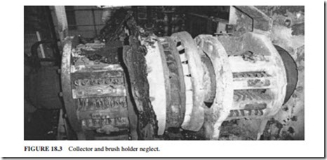
As the rotor ages, the bore copper, terminal studs, and copper coils become loose. The relative movement between the main lead and the number 1 coil will increase. This can lead to fatigue failure of the connection and a forced outage due to loss of field current. The insulation around the copper between the collectors and the number 1 coils can deteriorate, leading to a ground fault and a forced outage (Fig. 18.3).
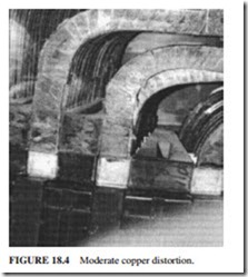
Copper Distortion. The copper winding becomes distorted in some generators after a long period of operation (Fig. 18.4). This problem occurs most frequently in the end wind- ing area. It is caused by the following:
● Frequent thermal cycling of the winding
● Overheating of the winding
● Use of soft or annealed copper
● Friction between the top turns and the retaining ring
The damaged copper should be repaired or replaced before returning the unit to service. Failure to do so can result in ground faults or interturn faults (shorted turns).
Forging Concerns
The rotor body is made of a single forging. It is not laminated because it experiences significant mechanical, electrical, and ther- mal stresses. The rotor forging should be inspected before rewind to determine the long-term structural integrity. This inspection becomes especially necessary in the following situations:
● If the unit has been exposed to negative sequence currents*
● If the unit has been operated as a motor
● If the forging was manufactured before 1960
Negative sequence currents can cause arcing between the wedges and the retaining rings, burning, hard spots, and cracking on
the surface of the forging. The rotors manufactured before 1960 tend to have lower tough- ness than modern rotors. They also have higher levels of impurities. This makes them mar- ginal for continued operation.
Recent inspection of some large steam turbine generators identified cracks in the rotor teeth and damage from in-service negative sequence events. This damage included strikes on the rotor teeth and the area of the retaining rings that faces the slot wedges. The cracks that occurred in the teeth of the rotor were in generators that experienced extended operations on turning gear.
The generator manufacturer should be consulted if there are negative sequence events. The manufacturer will examine the severity of the damage and recommend an inspection program for the rotor. The rotors, which experience extended periods of operation on turning gear, should also be inspected by the manufacturer.
The bore of the rotor forging should be inspected every 8 years if the generator experienced frequent start-stops. The rotor teeth and wedges should also be inspected using magnetic particle and fluorescent techniques, prior to 5000 start-stop cycles.
Retaining Rings
The main purpose of the retaining rings is to restrain the centrifugal force of the rotor wind- ing end turns (known as end windings). This centrifugal force is extremely large during normal operation. It produces a hoop stress that stretches the ring into a slight elliptical shape for two-pole rotors due to the uneven weight distribution of the end turns and associated insulation. The retaining ring is shrunk-fit at the end of the rotor body. This ensures that the retaining ring will remain cylindrical at full speed and prevents the ring from moving with respect to the body. The retaining ring will be subjected to high circulating cur- rents during unbalanced load conditions that lead to negative sequence currents in the rotor.
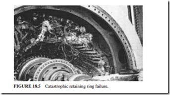
The retaining ring is made of two types of material: magnetic and nonmagnetic. The non- magnetic rings are used in large generators to reduce the leakage flux. The magnetic rings that were exposed to moisture developed corrosion. This led to failure during normal operation that resulted in extended outages. These magnetic rings were made from Gannalloy or 18% manganese and 5% chromium (18 Mn, 5 Cr). Both of these materials had serious problems. Gannalloy became embrittled when used in hydrogen-cooled generators. It is highly recom- mended to replace the Gannalloy retaining rings with ones made from 18% manganese and 18% chromium (18 Mn, 18 Cr). This material has been proved to be highly resistant to hydro- gen embrittlement. The retaining rings made from 18 Mn, 5 Cr were found to be subjected to stress corrosion cracking (SCC). Since the failure rate of the retaining rings due to SCC was high, these rings were replaced with 18 Mn, 18 Cr material. This material has also proved to be highly resistant to SCC. Catastrophic damage could occur if the retaining rings made from Gannalloy or 18 Mn, 5 Cr were not replaced with 18 Mn, 18 Cr (Fig. 18.5).
Misoperation
Misoperation of the generator rotor can cause catastrophic consequences on the rotor and secondary damage to the stator and prime mover. The reasons of misoperation include
● Operator error
● Equipment failure
● Abnormal system conditions
Figure 18.6 shows the most common modes of misoperation that can affect the rotor.


