After studying this unit, you will be able to answer these questions:
1 . How can electrical energy be converted into mechanical energy?
2. What is the theory and operation of the electric motor?
In your lessons on magnetism you learned that unlike poles of magnets are attracted to each other, but like poles repel each other. In the case of relays and sucking coils, you observed that this attractive force of magnetism can be converted into mechanical action.
HOW THE MOTOR WORKS
The ELECTRIC MOTOR is the most common method of converting electrical energy into rotating motion. Motors are used in thousands of ways in home and industry. They are used to heat and cool the home, to keep food cold, to wash clothes, mix food, and to ventilate the home. They are used in industry to provide power for cutting, shaping, and finishing materials into useful products. Our life would be a hard life and our standards of living would be much lower, if the electric motor were not yet created by science and invention
All motors operate on the principle of attraction and repulsion of magnetic poles. To understand this we will build a simple directcurrent motor and trace each step of its construction to discover the method of producing rotation by the interaction of magnetic fields.
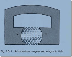
First, we must create a magnetic field, Fig. 10-1 . The familiar horseshoe magnet produces the field, with lines of magnetic force running from north to south. This is known as a FIELD MAGNET
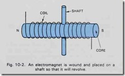
In our study of electromagnets we learned that if a coil is wound on an iron coil, a magnet would be produced. The polarity of the electromagnet would depend upon the direction of current flow in the windings. We will wind such a coil and also put it on a round shaft, about which it can rotate, Fig. 10 -2.
Assume that the current flowing will create the polarity as indicated in the drawing. This assembly is called the ARMATURE.
In Fig. 10- 3, the field magnets and the armature have been combined into one assembly.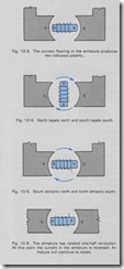
Carefully notice the polarity of both the field and armature magnets
Now a north pole will repel a north pole and a south pole will repel a south pole, so the armature will turn one quarter turn to the position shown in Fig. 10- 4. The arrows indicate the direction of rotation.
But, north and south poles attract each other, so the armature is caused to turn another quarter turn and will come to rest in the position shown in Fig. 10- 5.
No further rotation would take place. Remember that the polarity of the armature depended upon the direction of current flow.
Just as the north and south poles are lined up, change the direction of current flow in the armature by means of a switch. Then the situation would suddenly appear as in Fig. 10- 6.
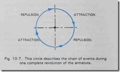
Is this position the same as when we started in Fig. 10- 3? It surely is. So the like poles repel each other for a quarter turn and then the unlike poles attract each other for the final quarter turn. One complete revolution of the armature has been accomplished. By reversing the current in the armature again the rotation would continue. As long as the current was reversed each one half revolution, the rotation would continue indefinitely. Fig. 10- 7 shows graphically the chain of events just described.
THE COMMUTATOR
Carefully notice the polarity of both the field and armature magnets. Now a north pole will repel a north pole and a south pole will repel a south pole, so the armature will turn one quarter turn to the position shown in Fig. 10-4. The arrows indicate the direction of rotation. It is necessary to change the direction of current flow in the armature at just the correct point to produce the continuing rotation. Of course we could not do this by hand with a switch. Some mechanical means is necessary and the device used to change the current in the armature is called a COMMUTATOR. Let’s see how it works. Carefully study the following description of the operation of a commutator.
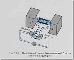
In Fig. 1 0-8 the ends of the armature coil are brought out to two pieces of metal, which are insulated from each other. Sliding on these metal sections are two spring metal contacts known as BRUSHES. A battery is connected to the brushes and arrows indicate the direction of current flow.
Current flows from battery to the brush (X), to commutator bar A, into the armature coil and out to commutator bar B, then through the brush (Z) to the battery.
Such current will make (C) of the armature a south pole and D a north pole. The repulsion and attractive force causes the armature to rotate one half turn. The commutator bars, of course, turn with the armature and the position of the armature after the half turn would appear as in Fig. 1 0- 9. Now the current flows from the battery to brush (X) to commutator bar B, into the armature coil and out through commutator bar A, through the brush Z back to the battery. Such a current will make C of the armature a north pole and D a south pole. In other words, the commutator has changed the direction of current flow through the armature. This occurs each half revolution and the conditions for continued rotation have been satisfied. If you did not understand this the first time you read it, follow the action through step by step until you have a clear picture in your mind of the underlying principles of electric motor operation.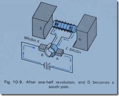
MOTOR CIRCUITS
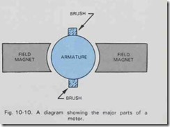
In the explanations that follow, the diagram in Fig. 10 -10 will be used to designate a motor. The various parts are named.
To improve the rotating force of the simple motor, it is possible to wind coils around the field magnets and make them strong electromagnets. Such windings are known as FIELD WINDINGS. An example of a SERIES type of DC motor appears in Fig. 10-1 1. In the series motor all of the current flows through the armature windings and the field windings. Such a motor varies its speed according to the load it must turn. It has the ability to start under heavy loads. The automobile starting motor is a series type motor.
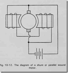
A second type of motor is the SHUNT or parallel wire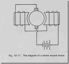 d motor, Fig. 10 -12. In the shunt motor, the current divides. Part flows through the armature windings and the remainder through the field windings. Such a motor tends to keep a constant speed under varying load conditions. It is very well suited to the operation of machine tools in a school or home workshop. There are other types of motors using both series and shunt windings that are known as COMPOUND motors. Detailed information about all of these DC motors can be found in textbooks on advanced electricity.
Further improvements are made upon our simple motor for commercial use. In studying the sequence of events as a motor completes one revolution, you will readily see that the turning force created by the interacting fields could be greatly improved if more field and more armature poles were used. The repulsive and attractive forces of magnetic fields decrease rapidly as the distance between them is increased. Mathematically speaking, the magnetic force between two poles varies inversely as the square of the distance between them. So by using more poles in a motor, the distance between poles is decreased and as a result the turning force is increased.
THE COMPLETE MOTOR
The field windings are wound on the field poles and the armature and commutator are mounted on a shaft. The whole assembly is placed in a shell or case. Suitable bearings are provided for the armature shaft. The case is provided with a means of holding the brushes under spring tension, so that they will constantly ride on the commutator bars. As the bars and brushes wear, the springs keep a constant brush pressure and assure a good electrical contact. Many motors have built in fans, which circulate air through the motor, thereby keeping the motor cool during operation.
Project 10 describes in detail the construction of an experimental TWO POLE MOTOR. This motor may be connected either as a series or a shunt wound motor. Study the action of the motor. Observe the function of the commutator.
MOTOR PRINCIPLES
The simple two pole motor described in this text and constructed in Project 1 is frequently called the St. Louis motor. Although this motor depends upon the interaction between the magnetic fields of the armature and the field windings, a more accurate description of the modern motor must include the action of a current carrying conductor in a magnetic field. Reviewing Unit 9 on Magnetism, you will recall that a magnetic field will exist around a conductor carrying an electric current. The left
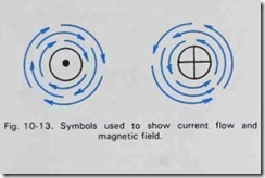
hand rule states, that if you grasp the wire by your left hand with your thumb pointing in the direction of current flow, your fingers around the wire will indicate the direction of the magnetic field. Symbols currently used to represent this phenomena are shown in Fig. 10-13. The dot in the center of the circle indicates the point of an arrow. The current is flowing toward you. The cross in the circle represents the feathers on the arrow as it goes away from you or into the paper. The circular arrows indicate the direction of the magnetic field in each instance
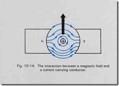
When such a current carrying conductor is in another magnetic field, there will be interaction between the fields which will cause motion. Observe this action in Fig. 10-14. The arrows show the direction of both the permanent magnet field and the field around the conductor. On the upper side, the conductor field opposes the permanent field (arrows in opposite directions). On the lower side, the conductor field reinforces the permanent field (arrows in same direction). The conductor will move toward the weakened field or up.
Coils of wire or conductors are used in the armature of a motor. The MOTOR ACTION between the two fields causes the rotation. In the dc motor, of course, the current is periodically reversed by means of
QUIZ UNIT 10
-
Write your answers to these questions on separate sheet of paper. Do NOT write in this book.
-
The rotating coils of the motor are called the .
-
A device to reverse the current flow in the armature windings is the .
-
Draw a diagram of a series motor.
-
List two characteristics of the series motor.
-
Draw a diagram of a shunt motor.
-
List two characteristics of the shunt motor.
-
Sliding contacts used to transfer electricity to armature are called .
-
List twelve devices or or pieces of equipment that use electric motors
