Voltage Dividers
Voltage dividers were discussed in Section 17–4 and will not be discussed extensively in this section. A voltage divider can be used to convert a higher voltage to a lower voltage for application requiring less voltage. Ohm’s law (presented in Chapter 14) is one of the most important concepts to understand. It states that the current through a circuit is directly proportional to the voltage across the circuit and inversely proportional to the resistance.
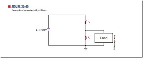
The example (Figure 36-40) is a practical example of a real-world voltage divider. The voltage source is the standard AC power source of 120V AC that has been converted to 120V DC (assuming no loss for this discussion). What is desired is a voltage-divider network that will divide this 120V DC source into a lower-voltage source specified by the manufacturer of a particular device (radio, cassette player, CD player, etc.). Assume the desired voltage is 6 volts, and the load will draw 200 mA. The remaining voltage will be dissipated as heat. Keep in mind that it is necessary to know the load current for the voltage required for the device in advance.
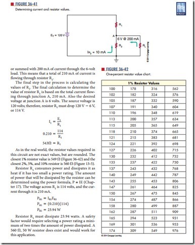
Referring to Figure 36-41, select the amount of cur- rent that is desired to flow through resistor R2 starts the process. In this example, an arbitrary value of 10 mA is chosen. This means that there is 10 mA of current flowing through R2 and the voltage at Junction A is 6 volts. Therefore R2 can be determined as follows:
or summed with 200 mA of current through the 6-volt load. This means that a total of 210 mA of current is flowing through resistor R1.
The final step in the process is calculating the values of R1. The final calculation to determine the value of resistor R1 is based on the total current flowing through junction A, 210 mA. Also the desired voltage at junction A is 6 volts. The source voltage is 120 volts; therefore, resistor R1 must drop 120 V 2 6 V, or 114 V.
Questions
1. How does a voltage divider convert a higher voltage to a lower voltage?
2. How can the load current be determined when it is not listed with a device?
3. Why was 10 mA determined as the current through r2 in Figure 36-41?
4. What is the voltage through r2 in Figure 36-41
and why?
5. What could be added to the circuit in Fig- ure 36-41 to insure the voltage is always 6 volts to the load?


