5.1 INTRODUCTION
As shown in Chapters 2 and 4, the induction machine configuration is quite complex. So far we elucidated the subject of windings and their mmfs. With windings in slots, the mmf has (in three-phase or two-phase symmetric windings) a dominant wave and harmonics. The presence of slot openings on both sides of the airgap is bound to amplify (influence, at least) the mmf step harmonics. Many of them will be attenuated by rotor-cage-induced currents. To further complicate the picture, the magnetic saturation of the stator (rotor) teeth and back irons (cores or yokes) also influence the airgap flux distribution producing new harmonics.
Finally, the rotor eccentricity (static and/or dynamic) introduces new harmonics in the airgap field distribution.
In general, both stator and rotor currents produce a resultant field in the machine airgap and iron parts.
However, with respect to fundamental torque-producing airgap flux density, the situation does not change notably from zero rotor currents to rated rotor currents (rated torque) in most induction machines, as experience shows.
Thus it is only natural and practical to investigate, first, the airgap field fundamental with uniform equivalent airgap (slotting accounted through correction factors) as influenced by the magnetic saturation of stator and rotor teeth and back cores, for zero rotor currents.
This situation occurs in practice with the wound rotor winding kept open at standstill or with the squirrel cage rotor machine fed with symmetrical a.c. voltages in the stator and driven at mmf wave fundamental speed (n1 = f1/p1). As in this case the pure travelling mmf wave runs at rotor speed, no induced voltages occur in the rotor bars. The mmf space harmonics (step harmonics due to the slot placement of coils, and slot opening harmonics etc.) produce some losses in the rotor core and windings. They do not notably influence the fundamental airgap flux density and, thus, for this investigation, they may be neglected, only to be revisited in Chapter 11.
To calculate the airgap flux density distribution in the airgap, for zero rotor currents, a rather precise approach is the FEM. With FEM, the slot openings could be easily accounted for; however, the computation time is prohibitive for routine calculations or optimization design algorithms.
In what follows, we first introduce the Carter coefficient Kc to account for the slotting (slot openings) and the equivalent stack length in presence of radial ventilation channels. Then, based on magnetic circuit and flux laws, we calculate the dependence of stator mmf per pole F1m on airgap flux density accounting for magnetic saturation in the stator and rotor teeth and back cores, while accepting a pure sinusoidal distribution of both stator mmf F1m and airgap flux density, B1g.
The obtained dependence of B1g(F1m) is called the magnetization curve. Industrial experience shows that such standard methods, in modern, rather heavily saturated magnetic cores, produce notable errors in the magnetizing curves, at 100 to 130% rated voltage at ideal no load (zero rotor currents). The presence of heavy magnetic saturation effects such as airgap, teeth or back core flux density, flattening (or peaking), and the rough approximation of mmf calculations in the back irons are the main causes for these discrepancies.
Improved analytical methods have been proposed to produce satisfactory magnetization curves. One of them is presented here in extenso with some experimental validation.
Based on the magnetization curve, the magnetization inductance is defined and calculated.
Later the emf induced in the stator and rotor windings and the mutual stator/rotor inductances are calculated for the fundamental airgap flux density. This information prepares the ground to define the parameters of the equivalent circuit of the induction machine, that is, for the computation of performance for any voltage, frequency, and speed conditions.
5.2 EQUIVALENT AIRGAP TO ACCOUNT FOR SLOTTING
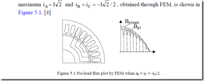
The actual flux path for zero rotor currents when current in phase A is
The corresponding radial airgap flux density is shown on Figure 5.1b. In the absence of slotting and stator mmf harmonics, the airgap field is sinusoidal, with an amplitude of Bg1max.
In the presence of slot openings, the fundamental of airgap flux density is Bg1. The ratio of the two amplitudes is called the Carter coefficient.
KC Bg1
When the magnetic airgap is not heavily saturated, KC may also be written as the ratio between smooth and slotted airgap magnetic permeances or between a larger equivalent airgap ge and the actual airgap g.
KC = gge≥1 (5.2)
FEM allows for the calculation of Carter coefficient from (5.1) when it is applied to smooth and double-slotted structure (Figure 5.1).
On the other hand, easy to handle analytical expressions of KC, based on conformal transformation or flux tube methods, have been traditionally used, in the absence of saturation, though. First, the airgap is split in the middle and the two slottings are treated separately. Although many other formulas have been proposed, we still present Carter’s formula as it is one of the best.
τs,r (5.3)
KC1,2 = τs,r − γ1,2 ⋅g / 2
τs,r–stator/rotor slot pitch, g–the actual airgap, and
![]() 4 bos,r / tanbos,rg − ln 1+ bos,rg 2 ≈ 52+b2os,rgbos,r2 (5.4)
4 bos,r / tanbos,rg − ln 1+ bos,rg 2 ≈ 52+b2os,rgbos,r2 (5.4)
γ1,2 = π g
g for bos,r/g >>1. In general, bos,r≈ (3 – 8)g. Where bos,r is the stator(rotor) slot opening.
With a good approximation, the total Carter coefficient for double slotting is
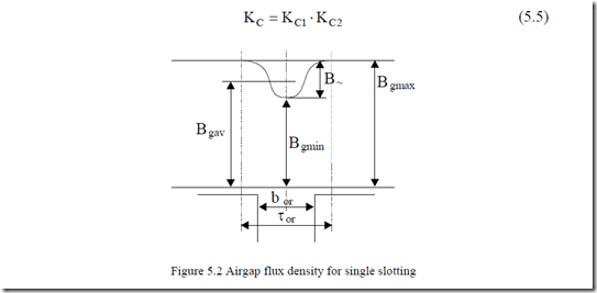
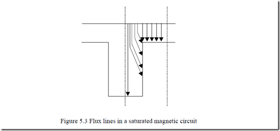
The distribution of airgap flux density for single-sided slotting is shown on Figure 5.2. Again, the iron permeability is considered to be infinite. As the magnetic circuit becomes heavily saturated, some of the flux lines touch the slot bottom (Figure 5.3) and the Carter coefficient formula has to be changed. [2] In such cases, however, we think that using FEM is the best solution. If we introduce the relation
B~ =Bg max −Bg min = β2 Bg max (5.6)
the flux drop (Figure 5.2) due to slotting ∆Φ is
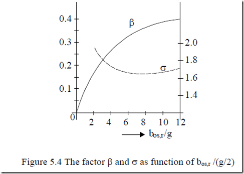
From [3], βσbos,r = g2 γ1,2 (5.8)
The two factors β and σ are shown on Figure 5.4 as obtained through conformal transformations. [3]
When single slotting is present, g/2 should be replaced by g.
Another slot-like situation occurs in long stacks when radial channels are placed for cooling purposes. This problem is approached next.
5.3 EFFECTIVE STACK LENGTH
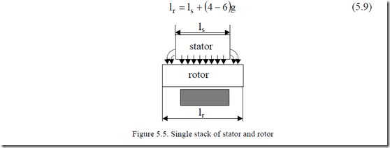
Actual stator and rotor stacks are not equal in length to avoid notable axial forces, should any axial displacement of rotor occured. In general, the rotor stack is longer than the stator stack by a few airgaps (Figure 5.5).
Flux fringing occurs at stator stack ends. This effect may be accounted for by apparently increasing the stator stack by (2 to 3)g,
lse = ls + (2 ÷3)g (5.10)
The average stack length, lav, is thus
lav ≈ ls +2 lr ≈ lse (5.11)
As the stacks are made of radial laminations insulated axially from each other through an enamel, the magnetic length of the stack Le is
Le = lav ⋅KFe (5.12)
The stacking factor KFe (KFe = 0.9 – 0.95 for (0.35 – 0.5) mm thick laminations) takes into account the presence of nonmagnetic insulation between laminations.
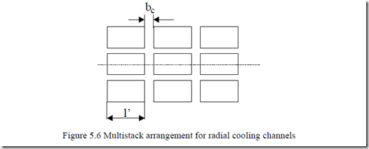
When radial cooling channels (ducts) are used by dividing the stator into n elementary ones, the equivalent stator stack length Le is (Figure 5.6)
