SINGLE-PHASE INDUCTION MOTORS
Single-phase induction motors are simple, robust and reliable, and are used in enormous numbers especially in domestic and commercial applications where 3-phase supplies are not available. Although outputs of up to a few kW are possible, the majority are below 0.5 kW, and are used in such applications such as refrigeration compressors, washing machines and dryers, pumps and fans, small machine tools, tape decks, printing machines, etc.
Principle of operation
If one of the leads of a 3-phase motor is disconnected while it is running light, it will continue to run with a barely perceptible drop in speed, and a somewhat louder hum. With only two leads remaining there can only be one current, so the motor must be operating as a single-phase machine. If load is applied the slip increases more quickly than under
3-phase operation, and the stall torque is much less, perhaps one third. When the motor stalls and comes to rest it will not restart if the load is removed, but remains at rest drawing a heavy current and emitting an angry hum. It will burn out if not disconnected rapidly.
It is not surprising that a truly single-phase cage induction motor will not start from rest, because as we saw in Chapter 5 the single winding, fed with a.c., simply produces a pulsating Xux in the air-gap, without any suggestion of rotation. It is, however, surprising to Wnd that if the motor is given a push in either direction it will pick up speed, slowly at Wrst but then with more vigour, until it settles with a small slip, ready to take-up load. Once turning, a rotating Weld is evidently brought into play to continue propelling the rotor.
We can understand how this comes about by Wrst picturing the pulsating MMF set up by the current in the stator winding as being the resultant of two identical travelling waves of MMF, one in the forward direction and the other in reverse. (This equivalence is not self-evident but is easily proved; the phenomenon is often discussed in physics textbooks under the heading of standing waves.) When the rotor is stationary, it reacts equally to both travelling waves, and no torque is developed. When the rotor is turning, however, the induced rotor cur- rents are such that their MMF opposes the reverse stator MMF to a greater extent than they oppose the forward stator MMF. The result is that the forward Xux wave (which is what develops the forward torque) is bigger than the reverse Xux wave (which exerts a drag). The diVerence widens as the speed increases, the forward Xux wave becoming progres- sively bigger as the speed rises while the reverse Xux wave simultaneously reduces. This ‘positive feedback’ eVect explains why the speed builds slowly at Wrst, but later zooms up to just below synchronous speed. At the normal running speed (i.e. small slip), the forward Xux is many times larger than the backward Xux, and the drag torque is only a small percentage of the forward torque.
As far as normal running is concerned, a single winding is therefore suYcient. But all motors must be able to self-start, so some mechanism has to be provided to produce a rotating Weld even when the rotor is at rest. Several methods are employed, all of them using an additional winding.
The second winding usually has less copper than the main winding, and is located in the slots which are not occupied by the main winding, so that its MMF is displaced in space relative to that of the main winding. The current in the second winding is supplied from the same single-phase source as the main winding current, but is caused to have a phase-lag, by various means which are discussed later. The combination of a space displacement between the two windings together with a time displacement between the currents produces a 2-phase machine. If the two windings were identical, displaced by 908, and fed with currents with 908 phase-shift, an ideal rotating Weld would be produced. In practice we can never achieve a 908 phase-shift between the currents, and it turns out to be more economic not to make the windings identical. Nevertheless, a decent rotating Weld is set up, and entirely satisfactory starting torque can be obtained. Reversal is simply a matter of reversing the polarity of one of the windings, and performance is identical in both directions.
The most widely used methods are described below. At one time it was common practice for the second or auxiliary winding to be energised only during start and run-up, and for it to be disconnected by means of a centrifugal switch mounted on the rotor, or sometimes by a time switch. This practice gave rise to the term ‘starting winding’. Nowadays it is more common to Wnd both windings in use all the time.
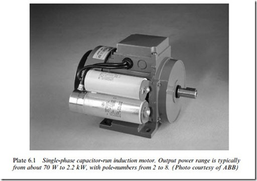
Capacitor-run motors
A capacitor is used in series with the auxiliary winding (see Figure 6.21) to provide a phase-shift between the main and auxiliary winding currents. The capacitor (usually of a few mF, and with a voltage rating
which may well be higher than the mains voltage) may be mounted piggyback fashion on the motor, or located elsewhere. Its value represents a compromise between the conXicting requirements of high- starting torque and good running performance.
A typical torque–speed curve is also shown in Figure 6.21; the modest starting torque indicates that the capacitor-run motors are generally best suited to fan-type loads. Where higher starting torque is needed, two capacitors can be used, one being switched out when the motor is up to speed.
As mentioned above, the practice of switching out the starting wind- ing altogether is no longer favoured for new machines, but many old ones remain, and where a capacitor is used they are known as ‘capacitor start’ motors.
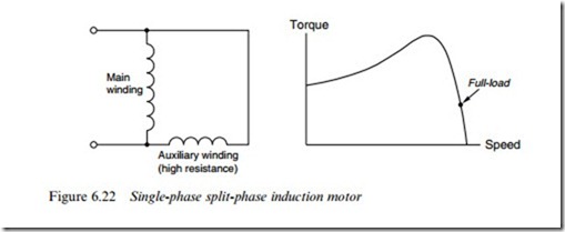
Split-phase motors
The main winding is of thick wire, with a low resistance and high reactance, while the auxiliary winding is made of fewer turns of thinner wire with a higher resistance and lower reactance (see Figure 6.22). The inherent diVerence in impedance is suYcient to give the required phase-
shift between the two currents without needing any external elements in series. Starting torque is good at typically 1.5 times full-load torque, as also shown in Figure 6.22. As with the capacitor type, reversal is accomplished by changing the connections to one of the windings.
Shaded-pole motors
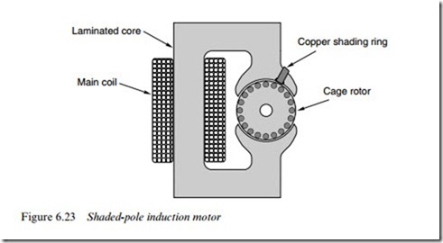
There are several variants of this extremely simple, robust and reliable cage motor, which predominate for low-power applications such as hairdryers, oven fans, tape decks, oYce equipment, display drives, etc. A 2-pole version from the cheap end of the market is shown in Figure 6.23.
The rotor, typically between 1 and 4 cm diameter, has a die-cast aluminium cage, while the stator winding is a simple concentrated coil wound round the laminated core. The stator pole is slotted to receive the ‘shading ring’, which is a single short-circuited turn of thick copper or aluminium.
Most of the pulsating Xux produced by the stator winding bypasses the shading ring and crosses the air-gap to the rotor. But some of the Xux passes through the shading ring, and because it is alternating it induces an e.m.f. and current in the ring. The opposing MMF of the ring current diminishes and retards the phase of the Xux through the ring, so that the Xux through the ring reaches a peak after the main Xux, thereby giving what amounts to a rotation of the Xux across the face of the pole. This far from perfect travelling wave of Xux produces the motor torque by interaction with the rotor cage. EYciencies are low because of the rather poor magnetic circuit and the losses caused by the induced
currents in the shading ring, but this is generally acceptable when the aim is to minimise Wrst cost. Series resistance can be used to obtain a crude speed control, but this is only suitable for fan-type loads. The direction of rotation depends on whether the shading ring is located on the right or left side of the pole, so shaded pole motors are only suitable for unidirectional loads.
Related posts:
Incoming search terms:
- characteristics of single phase imduction motor
- draw the operational characteristics of single phase induction motor
- Operating characteristics of a single phase induction motor
- single phase induction motor characteristics
- pick up single phase induction motor characteristics
- single phase induction motor opareting charateristics
- pick up the single induction motor characteristics
- pick up single phase motor characteristics
- pick up single induction motor characteristics
- performance characteristics of single phase induction motor
- operational characteristics of single phase induction motor
- operating characteristics of a single phase motor
- Draw operating characteristic of single phase IM
- their charateristics of capacitor start capacitor run induction motor


