Testing and Measuring Instruments
When using any instrument for testing or measuring electrical circuits, always consider your personal safety first. Know the voltage levels and shock hazards related to all wiring and equipment to be tested. Also be certain that the instrument used for the application has been tested and calibrated.
When taking readings with meters available with different ranges and functions-as in the case of a combination volt-ohm-ammeter-make certain that the meter selector and range switches are in the correct posi tion for the circuit to be tested.
If possible, the circuit being tested should be deenergized before at taching the meter or test leads to the desired test point. The circuit may then be energized to take the reading. Before disconnecting the meter, the circuit again should be deenergized.
VOLT-OHM-AMMETER
The volt-ohm-ammeter is one of the most useful testing instruments that the maintenance electrician can use (see Fig. 17-1). Some of its uses are as follows.
MEASURING INSULATION RESISTANCE. On partial grounds in motor windings, the insulation resistance can be measured with a voltmeter if the resistance of the voltmeter is known. The deflec tion of a voltmeter pointer is inversely proportional to the resistance of its circuit. Therefore, if E is the deflection measured rectly across the circuit, E’ the deflection measured through the insulation resistance, r the resistance of the voltmeter, andR the resistance of the insulation, then
The deflection measured directly across the circuit and also through the insulation resistance will be in volts, while r andR will be in ohms.
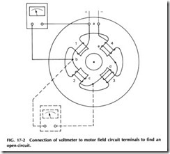
DETERMINING FAULTS IN FIELD CIRCUITS. To find an open-circuit field coil in an electric motor, first connect a source of voltage across the terminals of the field circuit as shown in Fig. 17-2 at a and e and apply the leads of a voltmeter successively to the field-coil ter minals (ab, be, etc.). No deflection of the voltmeter pointer will occur until the leads are applied to the terminals of the defective coil, and then the deflection will show the voltage between a and e.
Another method is to leave one lead of the voltmeter connected to one side of the circuit as at a and the other touched to successive coil terminals b, c, etc. No deflection will occur until the defect is bridged, and the voltmeter will then show the full voltage between a and e.
SHORT-CIRCUITED FIELD COIL. To find a short-circuited field coil, proceed as described for finding an open circuit but limit the current through the field circuit to a safe amount. The drop across the defective field coil, as indicated by the voltmeter, will be much less than that across any other coil.
FAULTS IN MOTOR ARMATURES. In winding an armature, it is advisable to test the winding for grounds and short circuits before the coils are connected to the commutator; any defective coils can then be replaced. The armature can be given an insulation-breakdown test by joining all the free ends of the coils together by means of a small wire and then connecting the series of coils to one terminal of a high-voltage trans former. The other terminal of the transformer is connected to the motor’s shaft. The alternating current to be applied for breakdown tests on com pleted motors is given in the following table:
SHORT-CIRCUITED ARMATURE COIL. A short-circuited armature coil can be found by sending through it an alternating flux, which will set up a current in the coil. Special testing transformers are normally used for this test. The transformer consists of a laminated iron core which has a width approximately equal to the length of the arma tures to be tested and pole-face curvature about the same as that of the armature cores.
When the transformer is placed over an armature core and an alter nating current is sent through the magnetizing coil, the alternating flux induces a voltage in the armature coils under the transformer poles; if any coil is short-circuited, the resulting current will heat it or will cause a piece of iron held near it to vibrate. By turning the armature through a complete revolution and holding a piece of iron over the coils being tested, any short-circuited coils are easily located. The transformer would not be put in position or removed while current is flowing through the magnetizing coil.
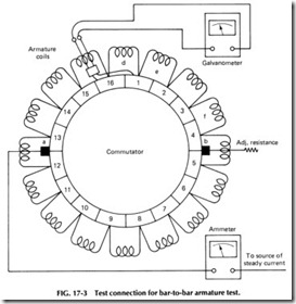
BAR-TO-BAR ARMATURE TEST. This test will reveal the exis tence and location of open circuits, short circuits, incorrect connections, and grounds in a completed armature. A steady current, adjusted to suit the requirements, is sent through the armature by terminals clamped to opposite sides of the commutator, and the leads of a voltmeter are con nected adjacent to the commutator segments by means of contact points insulated from each other and held a fixed distance apart by a block of wood or other insulation material. If there are no defects in the armature, the reading of the voltmeter will be the same for each pair of adjacent seg ments, because the drop of voltage is the same in all the coils. By trying several pairs, one can obtain a standard deflection, adjusting the current until this deflection is easily readable. If two bars are short-circuited or a coil is short-circuited, the voltmeter will show almost no deflection when the contacts are on the bars 1 and 3, 2 and 4, etc. A poor connection be tween a bar and the two coil leads belonging in it will be revealed by an unusually large drop between the bar and either adjacent bar. An open circuit in any coil prevents flows of current through that portion of the armature, and when the points bridge any two bars in the open section, the voltmeter will show no deflection until bars 9 and 10 (Fig. 17-3) are bridged, when the full voltage between terminals a and b will be im pressed on the instrument and the needle will be thrown violently. Crossed leads will cause double deflection when the points are on bars 6 and 7 or 8 and 9, because the voltage drop is then measured in two coils; between bars 7 and 8 the drop is normal in value but reversed in direc tion.
GROUNDED ARMATURE COIL. A grounded armature coil can be found by impressing full voltage on the test brushes, connecting one voltmeter lead to the shaft, and touching the other successively to each commutator bar. The deflection will be least when a bar to which the grounded coil is connected is touched.
MEGGER® TESTER APPLICATIONS
The Megger® Tester is a practical instrument used by electrical mainte nance and repair workers for conducting a wide range of tests with de pendable accuracy. It has earned the enviable distinction of being the most widely accepted device for measuring electrical resistance. For this reason every electrical worker should have a good knowledge of the Meg ger® Tester’s operation and the practical application of the meter.
One use of the Megger® Tester is for testing electrical systems after they are installed and before normal voltage is applied. This test is made after all the conductors, fuses or circuit breakers, panelboards, outlets, etc., are in place and connected. The current used for testing is produced by a small generator within the Megger® Tester that generates de power by turning a crank handle (also a part of the Megger® Tester).
The test is made by connecting the terminals to the two points be tween which the insulation test is to be made and then rapidly turning the handle (crank) on the Megger® Tester. The resistence in megohms can then be read from the dial. Satisfactory insulation resistance values will vary under different conditions, and the charts supplied with the Megger® Tester should be consulted for the proper value for a particular installation.
A similar test is often made with a magneto or small generator in conjunction with a de-operated bell. However, this is not nearly as reli able as the Megger® Tester since it does not give any indication of the in sulation resistance on a dial but merely rings the bell if there is any trouble on the lines tested.
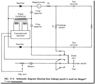
Most modern Megger® Testers have an additional terminal which is referred to as a guard terminal. This guard system is a means of prevent ing errors in the ohmmeter readings due to current leakage inside or on the outside of the instrument between the positive and negative sides of the circuit. Such leakage may be caused by dampness or dirt.
Figure 17-4 shows how the guard system is used. The guard ring is a
metallic washer supporting the line terminal and insulated from it. Any leakage current that may creep across the surface of the case or through materials from the positive ground (earth) terminal toward the negative line terminal will be intercepted by the guard ring. The guard circuit of fers a low-resistance path for the leakage current directly to the de source without passing through the deflecting coil of the ohmmeter. Resistance coils and other live parts inside the instrument are also mounted on guarded supports.
GROWLER FOR TESTING ARMATURES
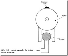
The growler has been around for a long time and is still a very good test ing device for use on electric motors. The growler operates on the same principle as a conventional transformer and is made up of a number of laminations secured together so a coil may be wound around the lami nated body of the growler. The growler acts as a primary side of the transformer, while the armature or stator coil acts as the secondary side. If there is a short in a secondary side, it will set up currents which will vibrate a thin piece of metal such as a section of hacksaw blade. A growler is always used on alternating current- never on direct current.
To use the growler, lay the armature on the growler as shown in Fig.17-5. Turn the armature around slowly in the growler and lay a section of hacksaw blade over each coil. A short-circuited coil will cause the blade to
vibrate. If any coil should get hot, then that coil is shorted. In fact, defec tive coils will normally get hot after being placed in the growler for only a minute or so.
When the blade is placed so as to make contact with the commutator bars and shaft, a spark will usually exist if there is a ground.
On open and closed circuits, the armature is laid on the growler, and a hacksaw blade is placed on the bars so as to make contact with two bars together. Somewhere on two or more bars, the test should cause a spark when the contact of the blade is made between them. This means the cir cuit is closed. If there are no sparks, the armature has an open circuit.
In using the growler to make the various tests, it is best to lightly scrape dirt from between commutator bars before starting any tests, assuring that a true test will result. Greasy commutators should be washed with gasoline and blown off or allowed to dry before performing the test.
For the price, the growler is one of the most useful test devices for troubleshooting motors of all kinds. Most maintenance shops have the tools and materials to construct any size growler necessary in a very short period of time. See Chapter 16 for complete details on constructing a growler for testing motor armatures or stators.
SPECIAL TESTERS
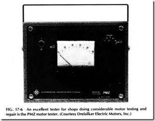
In recent years, many types of special motor testing instruments have become available. One is the Motor Tester PMZ as shown in Fig. 17-6. Tests of all types can be made with this instrument, and it is available from Dreisilker Electric Motors, P.O. Box 2758, Glen Ellyn, Illinois 60137.
Direct testing at the terminals and magnetic testing with test probes make this instrument suitable for detecting all motor deficiencies, including opens, short circuits, grounds, and an incorrect number of turns.
For direct measuring, the PMZ is connected with the main circuit connections of the test object. The state of the motor can be recognized before it has been detached. Faults on the terminals of field coils, carbon brushes, and collector segments can be easily determined. Test prods or a contact fork for the collector segments allow a quick contact.
Probes allow the testing of disassembled armatures or stators after the removal of the rotor by a quick scanning. Each fault can be exactly localized for each slot. The single probe 8 can be used for stators with a minimum hold 25 mm in diameter and a height of the bundle of lamina tions from 20 mm and for large motors with a slot up to 8 mm.
For direct measurement, the ac resistance of the stator or armature is measured at 2 kHz, thus allowing easy determination of faults and damages.
During the measurement with probes, the probe generates a magnetic field in the test object and takes up the reaction of faulty windings. The measuring instrument indicates exactly, and the built-in buzzer announces faults acoustically.
INSULATION BREAKDOWN TESTER UHZ
The insulation tester in Fig. 17-7 is capable of testing the insulation strength of electric motors and other equipment with high alternating voltage, offering a sine-shaped ac voltage steplessly adjustable from 0 to 2000 v.
A key lock prevents unauthorized use, and the high voltage potential is insulated from the ac line and isolated to ground, making the UHZ qualified for both permanent and field test areas.
The test voltage is attached to the test object by two hand-held, high-voltage, safety test probes. For tests requiring more than 2000 V, use an insulating safety cage or an automatic test system.
It is possible to switch the UHZ from test to burn. In the test posi tion, the high tension will be switched off within a few cycles of the mains if the insulation of the test piece breaks down. A buzzer indicates the fault. To locate the fault, switch the UHZ to the burn position and cutoff is delayed.
TESTING OF STEP MOTORS
Step motors are devices which translate electrical pulses into mechanical movements. The output shaft rotates or moves through a specific angu lar rotation per each incoming pulse or excitation. This angle or displace ment per movement is repeated precisely with each succeeding pulse translated by appropriate drive circuitry. The result of this precise, fixed, and repeatable movement is the ability to position accurately.
The testing of step motors can involve a variable assortment of tests and techniques. The wide variety of step motor applications and the cor responding variation in the tasks which are performed by them indicate that a particular motor will have to be tested based on its fu ction in the system.
When used with phase-switched inputs, a step motor can be a very nonlinear device. Its behavior may therefore vary under different load and drive configurations. The tests performed with a step motor should, insofar as possible, represent the actual conditions under which it is to be used. This is particularly true with open-loop tests when load configura tion and input pulse sequences can considerably affect the presence and location of resonant conditions.
Frequent testing is required by the user; this can include any com bination of the following tests, depending on the application:
1. Torque-speed characteristics with a specific drive scheme
2. Static torque characteristic as a function of position
3. Single step response
4. Static positional accuracy test
5. Velocity measurements
6. Closed-loop switch angle vs. speed measurements
7. Inductance measurement
In the open-loop mode this test generally involves driving the motor up to a particular speed and loading it slowly while continuously measur ing the torque until the motor is pulled out of synchronization. Due to the nature of step motors in the open-loop mode, the results of a torque speed test will, in general, depend on the drive scheme, the type of load, and the type of torque-measuring instrument.
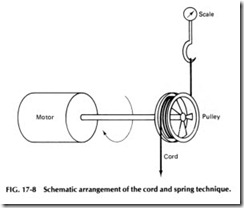
CORD AND SPRING SCALE. In this system a cord wrapped on a pulley is used to apply the frictional torque, and a spring scale is used for measurement. Figure 17-8 shows a schematic arrangement of this technique.
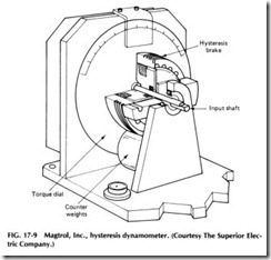
HYSTERESIS DYNAMOMETERS. This method uses a hystere sis brake for applying the frictional load and a gravity balance for mea surement of the torque. A commonly available unit from Magtrol, Inc., is
shown in Fig. 17-9. Although this unit shows a calibrated scale for torque readout, the newer units are available with a direct reading digital meter.
MAGNETIC PARTICLE BRAKE DYNAMOMETERS. A magnetic particle brake can provide a uniform, low-inertia load, which is ad justable with input current. The brake consists of a rotor surrounded by fine magnetic particles and enclosed in a nonrotatic housing. A coil, when energized, creates a magnetic field, which tends to solidify the particles, thus loading the rotor. The load torque is controlled by current in the coil.
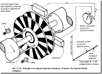
An optical torque-bar transducer provides an efficient torque measuring device for use with the particle brake. Figure 17-10 shows the principle of such a device available from Vibrac Corporation. An analog or digital readout is available which directly displays the torque.
DC MOTOR DYNAMOMETERS. The use of modern low-inertia servo motors and controls can provide an effective steady-state torque measuring system. The basic advantage of this type of dynamometer is that it can provide four-quadrant operation, and retarding torques can be measured.
Typical torque data obtained with the first three types of dynamom eters are shown in Fig. 17-11. The motor is an M093FC11 step motor run with the split resistor scheme, 24 V, 5 A/phase. The comments made earlier regarding each of these types of dynamometers appear to be de picted in these curves.
For closed-loop torque speed testing, the choice of dynamometers is less critical as the motor is inherently more stable and the various resonances are less predominant.
STATIC TORQUE MEASUREMENT. The static torque devel oped by a step motor varies with rotor position and stator current. The positional variation is cyclic and has a period in steps equal to the num ber of phases. Figure 17-12 shows a typical static torque curve for a 15° permanent-magnet step motor. The curves for two adjacent phases are shown when energized separately, and a third curve when both phases are energized together is also shown.
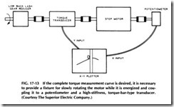
When the peak static torque is desired, it is possible to energize the motor and use a simple torque watch or a lever arm to get the data. How ever, if the complete torque curve is desired, it is necessary to provide a fixture for slowly rotating the motor while it is energized and coupling it to a potentiometer and a high-stiffness, torque-bar-type transducer. The optical unit from Vibrac is adequate.
Figure 17-13 shows a schematic of such a setup. The rotating assem bly should be geared for a slow-speed, low-backlash operation to allow proper data collections in the unstable portion of the torque character istic. An X-Y plotter is convenient for directly plotting the characteristic.
STEP MOTOR POSITIONAL MEASUREMENT. The measure ment of step motor position can be done with digital or analog trans ducers. For general response purposes a continuous rotation potentiom eter is quite adequate. This device should have a carbon film or conduc tive plastic element. The inertia should be low compared to the motor rotor inertia.
Continuous rotation potentiometers are useful for single-step or multistep responses as well as for plotting torque vs. position character istics. They are indispensable when damping studies are performed.
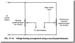
A voltage biasing arrangement using a second potentiometer as shown in Fig. 17-14 is useful for measuring small changes on an oscillo scope without a large voltage bias. It is also helpful for noise reduction to use a separate power supply or a battery for powering the poten tiometers.
STEP MOTOR VELOCITY MEASUREMENTS. Velocity information for step motors can be obtained directly with de tachometers or derived from a high-resolution encoder. Due to its ease of operation and utilization, the de tachometer is by far the more popular device. The volt age output of a de tachometer varies linearly with speed. This device is capable of giving transient as well as steady-state velocity measure ments.
A de tachometer can be of the iron core type or moving coil type. The iron core unit will have a ripple of 3-5%, while the moving coil type can have a ripple of less than 1o/o. An RC filter (typically 1 J-tF, 10 kO) is used to eliminate high-frequency noise. The frequency of the ripple depends on the number of commutator segments and is generally of the order of 7, 11, or 15 cycles per revolution. When a tachometer is used for measuring velocity variations on a motor shaft, care must be taken to account for the tachometer ripple.
TACHOMETER
Electrical tachometers are speed indicators used to indicate or record the speed of a machine or motor. The scales may be calibrated to read direct ly in revolutions per minute or feet per minute of any driven mechanism, such as a conveyor or motor drive. Tachometer scales may also be cali brated to indicate miles per hour, as in locomotive or railway speed ometers.
An electrical tachometer consists of a small generator belted or geared to the unit whose speed is to be measured. The voltage produced in the generator varies directly as the speed of the rotating part of the generator. Since this speed is directly proportional to the speed of the ma chine under test, the amount of the generated voltage is a measure of the speed. The generator is electrically connected to an indicating or record ing instrument which is calibrated to indicate units of speed. An electri cal tachometer is particularly well suited to the remote indication of the speed of a unit.

