Tools for Motor Repair
Good work in any trade requires good tools and, importantly, the knowl edge of how each is used. The motor repair field is no exception. Electri cians and maintenance personnel should be selective in choosing their tools, know how each is used, know how to care for them, and put them to their best use. Besides the conventional hand tools, there are many spe cialty tools that will make certain repair techniques easier to accomplish. Also, the host of power tools available on today’s market will help to ac complish the various tasks more quickly and usually in a more efficient manner.
This chapter is designed to describe the more common tools used in motor repair-including hand tools (usually purchased by repair work ers), specialty tools (some supplied by the plant, some purchased by repair workers), and power tools, which are almost always furnished by the place of employment. A careful review of these various tools will help the beginner or apprentice make the correct initial selection to act as a foundation on which to build a good assortment of tools necessary for motor repair. Even the experienced journeyman may find new and useful data on the use of tools to make jobs easier and work more efficient. Finally, supervisory personnel will have a good knowledge as to what tools may be necessary in the maintenance shop for motor repair and related situations.
While many major motor repair jobs have gone to automatic ma chines for their overhaul projects, there are thousands of smaller motor repair shops- including maintenance shops in most industrial plants that do not require such elaborate equipment. These smaller shops must stick to traditional tools and methods, utilizing the less expensive power tools so that the shops may reach their top efficiency.
To test and rewind motors efficiently, certain tools and testing equipment are necessary. Chapter 17 covered many testing devices that are suitable for use on electric motors. The list of tools that follow should be considered the minimum for each motor repairman. More may be added as the need arises.
1 16-oz machinist’s hammer
1 12-oz machinist’s hammer 1 Large screwdriver, 6 in.
1 Small screwdriver, 3 in.
1 #1 rawhide mallet
1 #2 rawhide mallet 1 Pair of tin shears 1 Knife
1 Flat file
1 Cold chisel
1 Lead scraper
1 Armature spoon
1 6 in. parallel plier
1 Set of soldering irons 1 Pair of scissors
1 Set of wedge drivers
1 Coil lifter and shaper 1 Long-nose plier
1 Diagonal plier
1 Set of coil tamping tools 1 8 in. side cutting plier
1 Hacksaw
1 Stripping tool for stripping open slot and stators
1 Coil hook to break coil ends loose from insulating varnish
1 Set of coil pullers for sliding top sides of coil into slots 1 Push cutter for trimming edges of slot insulation
1 Set of wire scrapers for removing insulation from ends of coil leads
1 Set of lead drifts for driving coil leads into commutator risers
1 Commutator pick for picking out short circuits between segments 1 Undercutting saw from undercutting commutator mica
1 Banding clamp for placing tension on banding wires while winding them
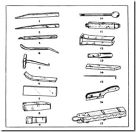
The use of most of the tools listed will be fully explained in the chap ters on motor winding. See Fig. 18-1.
FIG. 18-1 Some of the specialty tools traditionally used for rewinding motors.
(1) stripping tool for stripping open slot armatures and stators. (2) coil lifter for lifting coils from the slots. (3) lead lifter for lifting coil leads from commutator risers. (4) lifting tool for prying tight coils from slots. (5) coil hook to break coil ends loose from insulating varnish. (6) coil puller for sliding top sides of coils into slots. (7) fiber slot drift for driving coils into slots (four thicknesses needed: 3/16″, 5/16″, 7/16″, and 9/16″). (8) fiber coil shaper for shaping coil ends after coils are in slots. (9) steel slot drift for driving coils to the bottom of partly closed slots. (10) push cutter for trimming edges of slot insulation. (11) wedge driver for driving wedges into partly closed slots. (12) wire scraper for removing insulation from ends of coil leads. (13) lead drift for driving coil leads into commutator risers.
(14) one-sided chisel to cut off leads at risers. (15) commutator pick for picking out short circuits between segments. (16) under-cutting saw for under-cutting commutator mica. (17) banding clamp for placing tension on banding wires while winding them. (Courtesy Page Power Co.)
THUMM MACHINES
While the electric repair industry does not recognize the THUMM machine as the most economical or the most necessary equipment, Dreisilker Electric Motors, Inc. has been using this machine for their electric motor overhauling since 1968. It is used to strip electric motor stators and rotors as follows.
COIL CUTOFF AND COIL PULLING IS DONE ON ONE MA
CHINE. A stator is placed on the turntable of the THUMM machine
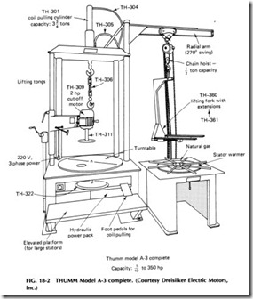
with the connection side of the winding up. The stator is then quickly and firmly locked to the turntable. The cutoff motor with the saw blade is then lowered into the stator. The rotating saw blade is pressed into the winding just above the end of the laminations. Then by rotating the turn table the winding is quickly cut off. The stator is then taken off the turn table and placed on the stator warmer with the cutoff end down. The stator is heated up within minutes to soften and loosen the coils and insu lation. The flame of the warmer will not touch the stator. The stator is then returned to the turntable and fastened down with the winding facing up. A hydraulic cylinder hooked to specially designed tongs will lift out all the coils and slot insulation with ease.
This process is one of the fastest, most economical ways to strip stators. No afterburners are required since no smoke is generated. No air purifiers are needed. The process leaves hardly any odor. Stators are not being distorted and can be wound immediately.
Armatures are stripped in the same fashion with the AZM-2000 rotor rebuilding machine.
The THUMM coil puller in Fig. 18-2 shows the unit in all its simplic ity and ease of accessibility. The coil puller is available in four different
models to accommodate stators from 11!2 to 59 in. in diameter and rotors to 47 in. in diameter.
The THUMM coil puller with its self-contained hydraulic power pack system is the fastest and most modern coil cutoff and stripping ma chine in the world. All that the THUMM machine requires for operation is 230 or 460 V, three phase. It is the most versatile, compact, and rugged coil puller and stripper on the market today. This machine is an econom ical time- and labor-saving device.
TO CUT OFF THE WINDING HEAD. To cut off the winding head, the stator is placed on the ball-bearing-supported rotating plat form. By turning the crank on the left side of the machine, the winding head cutter is positioned to the proper cutting height. The cutting wheel is then pressed back against the windings. By rotating the platform against the running direction of the cutting wheel, the winding head is cut. This procedure is repeated until the winding head is separated. The cutting wheel is then moved back to the center of the stator, raised, and swung out of the way.
WARMING OF STATORS. The warming of the stators can be done in a uniform, fast, and inexpensive way on the propane- or natural gas-operated stator warmer.
LIFTING THE COILS. To lift the coils, the stator must be turned (coils up). With special lifting tongs the coils are firmly gripped and hy
draulically lifted so that complete coil groups are lifted out each time. The vertical movement is controlled by a foot lever, thus leaving both hands free to guide the lifting tongs.
The foregoing features are summarized and emphasized as follows:
1. Considerable savings in time and energy.
2. Coil cutoff and coil lifting are done on one machine.
3. Absolutely clean cutting and pulling.
4. Quick and secure locking of stators and rotors.
5. Vision is unrestricted since the fastening devices are under the table.
6. The platform is mounted on ball bearings; therefore, the stator is easily rotated.
7. Housing and lamination damage is entirely eliminated.
8. The gas stator warmer loosens coils and insulation without the use of chemicals.
9. Foot-lever-operated hydraulic system.
10. Compact and rugged construction.
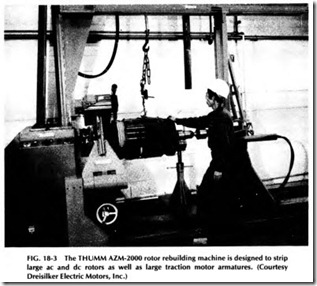
The THUMM Model AZM-2000 rotor rebuilding machine (Fig. 18-3) is designed to strip large ac and de rotors as well as large traction motor armatures. The machine comes complete with winding head cutoff and self-contained, hydraulic pulling cylinders. Standard or special tongs are available for pulling windings.
The windings can be easily pulled out with either of two built-in hy draulic cylinders. The cylinders pull vertically and horizontally with 6615 lb (3000 kg) of pulling force and are operated by a foot pedal.
The rotor is placed between the chuck and tailstock. The variable speed drive changes the rotating speed of the rotor to any required speed. The winding head cutoff unit is mounted in front of the headstock. It is adjustable and movable. With a wheel, it can be moved horizontally parallel to the rotor. By means of a handwheel, the position of the cutoff unit can be varied to fit rotors up to 47 in. (1200 mm) in diameter and 67 in. (1700 mm) long. The maximum rotor weight is 7700 lb (3500 kg).
The cutoff unit also can be rotated to bring the cutoff wheel parallel to the rotor (for undercutting commutators, etc.).
The rotor windings can be cut off on either side. Rotors can be warmed on the machine through an open gas flame or infrared heating.
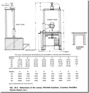
Dimensions of the various models of THUMM machines are shown in Fig. 18-4.
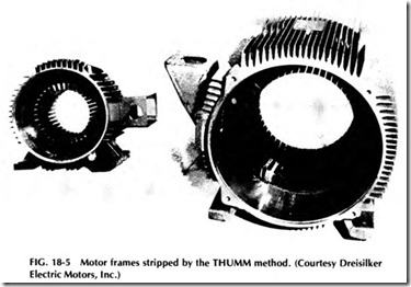
Stripped frames by the THUMM method are shown in Fig. 18-5.
Even aluminum frames, including new-design high-efficiency motors, can be stripped safely and easily with the THUMM method. No damage is
done to either the aluminum frame or the laminations.
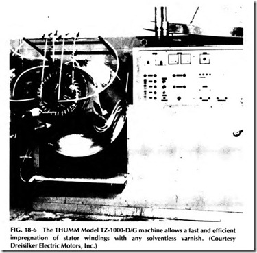
The THUMM model TA-1000-D/G machine (Fig. 18-6) allows a fast and efficient impregnation of stator windings with any solventless var nish. This design advantage eliminates time-consuming dipping and (oven) baking, thus facilitating more efficient motor repair.
The stator is mounted flat against the plate guided by the center bore, which guarantees an absolutely concentric position. The turntable with stator is automatically rotated and can be tilted to a 90° angle. The speed rotation is controlled by a single-speed, two-speed, or variable speed motor.
The stator winding is heated through a three-phase variable-voltage transformer, and the trickling and/or hardening temperature is sensed and controlled without physical contact. Varnish is forced from the reser voir to the trickling jet by air pressure. All resins are usable with a vis cosity up to 12,000 cps.
The advantages of this machine over the conventional methods are as follows:
1. Simple operation through automatic temperature and voltage control.
2. Leaves varnish only on the windings.
3. Continuous work procedure-stator can be processed immedi ately.
4. Reduced overall time provides faster deliveries.
No cleaning of metal parts necessary.
6. No resin loss.
7. Even and excellent slot fills.
8. Effective hardening even between fine wires and in long slots.
9. Total mechanical binding of windings.
10. High moisture resistance; no danger of causing water conden sation in winding.
11. Better heat sink.
12. Varnishing of stators through the trickling method results in high quality and at the same time reduces cost.
13. Slip ring and de armatures can be trickled.
ABISOFIX ISOLEX
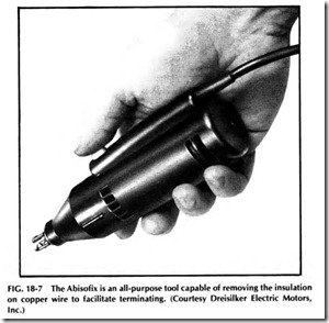
The Abisofix (Fig. 18-7) is an all-purpose tool capable of removing the in sulation on copper wire to facilitate terminating, that is, soldering the wire ends of stator and transformer coils and the like. This tool is simple to operate and easy to reset. The operator has only to select the correct speed step from a potentiometer for different wire sizes.
An electric motor drives an arrangement of three counterbalanced knives which close in around the wire by centrifugal force. The centrifugal force is governed by the speed of the motor, which in turn is con trolled by a potentiometer. This speed control enables the tool to be set for various wire gauges; fine wires require low speed, whereas heavier
wire requires higher speeds.
Because of the tool’s compact design, it is possible to strip to within 1mm of the soldering point. It is also possible to reach points on the ter minals of motors and transformers which are not easily accessible.
The Abisofix can be used for removing the insulation from the following:
Enameled copper wire
• Resistance wire
• Silk-, glass-, or polyester-covered wire-35 to 11 AWG
With the addition of a special device, it can also be used for stranded wire (silk or plastic) from 30 to 10 AWG.
METAL TURNING LATHE
The metal turning lathe is a very valuable asset to any maintenance shop- so much so that no shop can really afford to be without one.
When selecting a lathe for motor repair, the most important factor to consider is the size of work that will be machined on the lathe. In gen eral, this is determined by the greatest diameter and length of work. The lathe selected should have a swing capacity and distance between centers at least 10o/o greater than the largest job that will be handled. The buyer, however, must use discretion when purchasing a lathe for the machine shop. For example, if the majority of the armatures to be turned are less than, say, 7 in. in diameter-with only two or three motors in operation that are larger-it would be impractical to purchase a lathe to handle the larger motors which may only need overhauling once every 5 years or so. Since the majority of the work will be under 7 in. in diameter, a lathe with a 7-in. swing would suit the shop better. Then, when the larger motors re quired repairs, they could be sent to a large repair shop. By doing so, the maintenance shop could cut expenses considerably.
If the lathe required is a large one, say, with a 13-in. swing or more, the lathe should be equipped with its own supporting structure. On the other hand, if a 7- or 9-in. model is required, either a bench lathe or a small cabinet model may be selected.
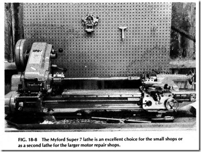
For the repair shop doing work on small motor armatures or as a sec ond lathe for the larger shops, no better lathe can be found for the price than the Myford Super 7 (Fig. 18-8). It will handle armatures up to 7 in. in diameter.
In overhauling armature commutators of electric motors, the com mutator segments are first trued by taking a light, accurate cut with a carefully ground cutting tool. Then the mica insulation is undercut, usu ally by using a special motor-driven undercutting attachment designed especially for this application alone.
To perform this operation, the motor armature shafts- with center holes countersunk- are mounted between lathe centers and driven with the faceplate and lathe dog. In mounting the shaft, make certain that both center holes are free from burrs and dirt. If the shafts do not contain center holes, one end of the shaft is mounted in a three-jaw universal chuck, and the other end is supported by a Jacobs Center Rest Chuck. In
using the latter, tighten the bronze jaws just enough to remove looseness but not enough to cause drag. During the turning, be sure to apply plenty of lubricant on the shaft at the point of bearing with the jaws of the center rest chuck.
Besides being used for motor repair work, the lathe can also be used to perform many other useful shop tasks, such as turning and threading machine screws, making parts for motors or motor repair tools, and making custom tools to fit a particular need.
For further information on the Myford Super 7 lathe, contact D & M Model Engineering, P.O. Box 400, Western Springs, Illinois 60558.
MOTOR REPAIR MATERIALS
The proper insulation of a stator or armature means the insulation of the slots as well as the coils, the former serving the dual purpose of insulat ing and mechanically protecting the coils at the same time. These insula tions may be divided into groups which indicate the purpose for which they are most suitable. In the first group may be listed strictly electrical insulations such as cotton tape, oiled cloth of cotton muslin or linen, var nished cambric, varnished muslin, varnished silk, and other types of insu lating cloths.
In the second group, the materials affording the greatest mechanical protection include pressboard, hard fiber, vulcanized fiber, and fish paper. Those insulators especially adapted to high temperatures fall in the third group and include mica, micanite, mica paper, glass tape, and mica cloth. From this it would seem that there is an insulation for prac tically every purpose, and a certain degree of care must be exercised in choosing the insulation for any particular job. The best advice is to ob tain the catalogs from the various suppliers of insulating materials and become completely familiar with each, reading the descriptions and speci fications of each. Then the winder will have a good basic knowledge with which to make the proper selection.
Related posts:
Incoming search terms:
- tools used to connect an electric motor
- pdf list of tools used in motor rewinding
- All hand tools for rewinding a 16 slot motor price
- Types and uses of motor rewinding tools
- tools use in disassemble dc generator
- Tools required for motor winding
- Tools for rewinding a motor and their use in winding
- tools for putting a coil in a stator
- Spinal and other tools for reparing motor
- potential tools used to rewind
- Motor winding Tools
- moter tool
- Mention the instrument used to connect motor machine
- Instrument used for rewinding
- Instrument for describing motor winding
- each tools of motor by name
- write 10 Winding tools and explain
