Troubleshooting de Motors
A new de motor should always be thoroughly tested before being put into operation and, likewise, should be tested periodically throughout its use ful life. By the same token, any motor that is repaired should again be tested before it is put back into service.
GROUND TEST
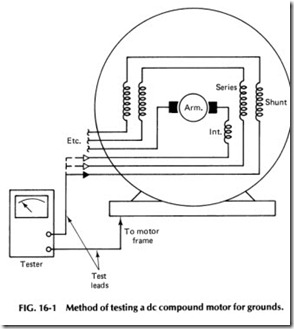
The fields, armature, and brush holders should be tested for grounds by first disconnecting all external leads. Then use a continuity tester by placing one test lead on the frame of the motor and then touching the other test lead to each motor lead in succession as shown in Fig. 16-1. The tester should not register. If it does, a ground is indicated either in the field circuit or in the armature circuit. Determine which.
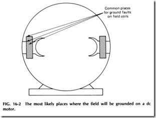
Figure 16-2 shows the most likely areas in which a ground will occur. A grounded field coil may be burned and have several wires damaged or broken, requiring a complete rewiring of the field. If a ground is located on the series fields, the interpole, or the shunt fields, it will be necessary to remove the fields from the frame and reinsulate them.
TEST FOR OPENS
The method of testing for opens will vary from motor to motor depending on whether it is series, shunt, or compound wound. In a small series motor, for example, only two leads are used for connection to the line; the
field and armature windings are made internally. When the test leads are connected to these two motor leads, the lamp should light, or the indi cator moves on the dial to indicate a complete circuit. If the lamp does not light, the problem could be any of the following:
1. Brushes not making contact with the commutator
2. A broken wire in the field
3. A broken connection between fields
4. A wire disconnected or broken on the brush holder
This same test may be used on large series motors with external leads to field and armature. However, on de motors with more than one circuit (shunt, two; compound, three) and when only two leads are brought out of the motor, the motor must first be disassembled before the tests can be made.
ARMATURE TESTING
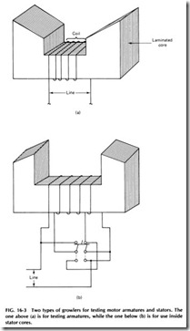
One of the most common devices found in maintenance shops for testing motor armatures is the growler, which is constructed of laminated iron in the form of a core around the center of which a coil of insulated wire is wound as shown in Fig. 16-3. When this coil is connected to an alternat ing current source, it sets up a powerful alternating magnetic field at the two poles of the growler.
Note in the illustration that growlers are made with poles shaped at an angle, so that armatures of different sizes can be laid in these poles.
Growlers are also made with poles shaped with the angle in the opposite direction (as shown) so they can be conveniently used on the inside of large alternating current windings.
The growler on the right in Fig. 16-3 has its windings arranged in two separate coils, and the leads are connected to a double-throw, double pole switch, so that the coils can be used either in series or parallel by changing the position of the switch. This permits the growler to be used on either 120 or 240 V and also makes possible an adjustment of growler field strength for testing windings with different numbers of turns and high or low resistance.
When an armature is placed in a growler and the current turned on in the coil, the flux set up between the poles of the growler builds up and collapses with each alternation, thus cutting across the armature coils and inducing a voltage in them in a manner similar to the action in a transformer. If there are not faults of any kind in the armature winding, no current will flow in the coils from the voltage induced by the growler.
However, if there is a short circuit between two of the commutator seg ments or within the turns of a coil, an alternating current will flow in this shorted coil when it is placed at right angles to the growler flux. This sec ondary current, which is flowing in the armature coil, will set up alternat ing flux around it and in the teeth or edges of its slots.
Now if a thin piece of steel is held over the opening of this slot- such as a piece of hacksaw blade- the steel will vibrate rapidly. A short circuit is the only fault that will give this indication, so it is a very simple and excellent way for locating shorted armature coils.
It is best to perform all tests with a growler on coils that are in the same plane of the growler flux; that is, as the test is made from one slot to the next, the armature should be rotated to make the tests on all coils in the same position.
An ammeter is sometimes used in conjunction with a growler. The two leads of the ammeter are placed across a pair of adjacent commutator bars which connect to a coil lying in the growler flux, and the ammeter should show a definite reading. If the test is continued around the com mutator, testing pairs of adjacent bars while rotating the armature to make the test on coils which are in the same plane, each pair of bars should give the same reading. In the case of a faulty coil, the reading may either increase or decrease, depending on the nature of the fault.
When testing wave-wound armatures, if the leads of two coils are shorted, the indication will show up at four places around the armature. Figure 16-4 shows a winding for a four-pole wave armature in position for testing in a growler. The heavy lines represent two coils which complete a circuit between adjacent commutator bars, 1 and 2 (see Fig. 16-5). The top side of one of these coils and the bottom side of the other connect at bar 10. Note that a short circuit between bars 1 and 2 would cause the steel strip to vibrate over the four slots shown by the small double circles.
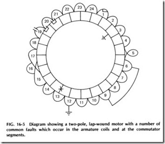
In addition to short circuits, a number of other problems may occur in de motors. They include grounded coils or commutator bars, open coils, shorts between commutator bars, and reversed coil leads. In addi tion to the growler, which can be used to locate any of these faults, a gal vanometer and battery may be used to locate many of these troubles by testing at the commutator bars.Figure 16-5 shows a diagram of a two-pole winding with a number of the more common faults which may occur in armature coils and at the commutator segments. In reviewing this diagram, note that coil 1 is shorted within the coil, which is probably the result of broken or dam aged insulation on the conductors. To test for this fault, place the arma ture on the growler and close the switch to excite the growler coil. Place a thin steel strip over an armature slot which is at least the distance of one coil span from the center of the growler core. Tur the armature slowly, keeping the steel parallel with and over the slots. When the slot contain ing coil1 is brought under the steel, the induced current flowing in this local short circuit will set up flux between the teeth of this slot, which will attract and repel the steel strip, causing it to vibrate like a buzzer. This indicates that the coil is short-circuited. Mark this slot with a piece of chalk and proceed with the test. Again rotate the armature slowly and test each slot, at all times keeping the strip over slots that are in the same position with respect to the growler. When the slot which contains the other side of the shorted coil is brought under the steel strip, it will again vibrate. Mark this slot also. The two marked slots should now show the span of the exact coil which is shorted.
If no other slots cause the steel to vibrate during the test, there is only one short in the armature. This test will apply to armatures of any size, regardless of the number of poles in their winding and whether they are wound lap or wave.
To locate the bars on the commutator to which the leads of the shorted coils are attached, use the ammeter, placing the two test leads on two adjacent bars. Note the reading on the meter carefully and, by rotat ing the armature, check the readings of all the other bars in this same position. When the test leads are placed on the bars that connect to the shorted coil, the reading will be lower than the other readings obtained.
In testing for loose coil leads, such as the ones shown on coils 20 and 21 of Fig. 16-5, the growler and thin strip will not show any vibration at any slot. However, the ammeter may be used (with the growler) by test ing between commutator bars. When the ammeter leads are placed on the commutator bars to which these coils are connected, the reading between them and adjacent bars would drop to zero, indicating an open circuit.
The open circuit shown in coil19 in Fig. 16-5 can be found by testing around the commutator with an ammeter. When the test leads of the am meter are placed across the bars to which the open coil is connected, a very low reading will be obtained. The reason for any reading at all is because there are always two paths for the current to travel through the winding, unless it is open at some other coil also. With an open circuit only at coil19 in the diagram, there would still be a circuit through all the other coils in series. The voltages induced in the coils which lie in the ac tive position for the growler flux would tend to neutralize each other, but there is often a slightly unbalanced condition in the windings which would allow a little current to flow through the ammeter.
If there are, say, three coils of the armature in the active flux of the growler and one side of coil 19 (see Fig. 16-5) is one of these, then there will be three good coil sides working against two good coil sides with their induced voltages, and since coil 19 is open-circuited, the ammeter reading would be about one third normal. The exact amount of the read ing, however, will depend on the pitch of the coils and the size of the armature. Be sure to remember that one open circuit in an armature does not necessarily give a zero reading on the ammeter unless the coil sides on each side of the test points are perfectly balanced electrically.
REVERSED COIL
Coil5 in Fig. 16-5 is reversed. Neither the growler with the steel strip nor the growler with the ammeter will show this fault, because the induced current is alternating and the motor will not indicate the reversed polar ity of the coil. However, if the test leads of the ammeter are spread far enough apart to touch bars 1and 3, two coils in series will be tested. Then place the test leads on bars connected to coils 4 and 5 or 9 and 6 (two coils will be in series in either case), and it can be found that the voltage in one will be opposite in direction to that in the other, causing the reading to be zero. To summarize, in testing for reversed coils, the test leads are placed on the proper bars to test an extra commutator segment, and the indica tion for the reversed coil will be a zero reading.
GROUNDED COILS
Coil 12 in Fig. 16-5 is grounded, but the growler and steel strip test, or the bar-to-bar test with the ammeter, will not indicate this fault. To locate a ground, the test leads are placed one on the commutator and one on the shaft or core of the armature. If the first test is made between the bar of coil 8 and the shaft, a very high reading would be obtained on the ammeter, because this would give the reading of the four coils in series between the grounded coil and this bar.
As bars are tested closer to the grounded point, the reading will gradually decrease, and the two bars that give the lowest reading should be the ones connected to the grounded coil. The sum of the readings from these two bars to the shaft should equal the reading of a normal coil.
SHORTS BETWEEN COILS
In referring again to Fig. 16-5, it is found that coils 6 and 9 are shorted together, which places coils 6, 7, 8, and 9 in a closed circuit through the short and the coil connections to the commutator bars. In this case, the growler and steel strip will vibrate and indicate a short circuit over each of the slots in which these coils lay. A bar-to-bar test with the ammeter leads would not give a definite indication, but the readings on these bars would be lower than normal.
REVERSED LOOPS
Coils 15, 16, and 17 in Fig. 16-5 are connected properly to each other, but their leads are connected to the wrong commutator bar. To detect this, use the bar-to-bar test with an ammeter. In doing so, the meter will show double readings between bars 1 and 2, normal readings on bars 2 and 3, and double readings again on bars 3 and 4. This indicates that the coils are connected in proper relation to each other but that their leads are crossed at the commutator bars.
SHORTED COMMUTATOR SEGMENTS
Coil13 in Fig. 16-5 has a short between its commutator bars. To detect this fault, the growler and thin steel strip may be used, in which case the steel strip would vibrate, indicating a short circuit over both slots in which this coil lies. The bar-to-bar test of the ammeter will give a zero or very low reading across these two bars, depending on the resistance of the short circuit between them.
If the winding is connected lap, the short would be indicated in two places on the core, and if it is connected wave for four poles, it would be indicated in four places on the core.
GROUNDED COMMUTATOR SEGMENTS
Assume that the commutator bar to which coils 2 and 3 are connected in Fig. 16-5 is grounded to the shaft. The growler and steel strip will not indicate this fault. The ammeter used in conjunction with the growler, with tests made between other commutator bars and the shaft, would show high readings on the meter, but as bars are tested closer to the grounded one, the reading falls lower and lower and will be zero when one test lead is on the grounded bar and the other on the shaft. If an absolute zero reading is obtained, it indicates the ground is at the commutator bar.
GALVANOMETER TESTS ON ARMATURES
A galvanometer is a measuring device for indicating very small electric currents. The D’Arsonval galvanometer is the most common type and is widely used in the electrical industry. Its indicating system consists of a light coil of wire suspended from a copper ribbon a few thousands of an inch wide and less than .001 in. thick. This coil, free to rotate between the poles of a permanent magnet, carries a small mirror which serves as an optical pointer and indicates the coil position by reflecting a light beam onto a fixed scale. The torque which deflects the indicating element is produced by the reaction of the coil current with the magnetic field in which it is suspended.
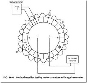
Figure 16-6 shows a method of making galvanometer tests on arma tures. Two leads from a de power source should be held against bars on opposite sides of the commutator and kept in this position as the arma ture is rotated. This will send a small amount of direct current through the coils of the winding in two paths in parallel.
If the positive lead in Fig. 16-6 is on the right, a current will flow from this lead through the commutator bar to the right-hand side of the winding. If all coils of the winding were closed and in good condition, the current would divide equally, part flowing through the top section of the winding to bar 3 and the negative lead and the other part flowing through the lower section of the winding to the same bar and lead. When this cur rent is flowing through the armature and a test is made between adjacent bars with the galvanometer, the instrument reads the voltage drop due to the current flowing through the resistance of each coil. So the galvanom eter test performs quite similarly to the test with the ammeter and growler.
In testing for an open circuit with the galvanometer leads placed on adjacent bars connected to good coils, there will be no reading in the section of the winding in which the open coil is located, but when these leads are placed across the bars connected to the open coils, the needle will probably jump clear across the scale, because at this point it tends to read practically the full de voltage.
Of course, if there are two open circuits in this half of the armature, no reading will be obtained at any pair of bars. This is a good indication that more than one open is present. If a test is made all the way around the commutator and no open circuits are present, the galvanometer should read the same across any pair of bars. You should be careful, how ever, to secure at all times a good contact between these test leads and the bars and also be certain that the battery or de voltage leads made a good connection to the commutator as the armature is rotated. Other wise, variations in the readings will be obtained.
A reading lower than normal between any two bars will indicate a shorted coil, and a zero reading indicates a short between two commu tator bars. When galvanometer leads are placed on bars 2 and 3, which are connected to coils with their leads transposed, the reading will be nor mal, but in testing between bars 1 and 2 or 3 and 4 the reading will be double. This indicates that the leads at bars 2 and 3 are the ones reversed.
REMOVING FAULTY COILS
In many cases when a motor develops problems, it is inconvenient to take it out of service for complete rewinding or for the amount of time required to replace the defective coils with new ones. At times like these, when it is extremely important that a machine be kept in service to avoid delays in production, a quick temporary repair can be made by cutting the faulty coils out of the armature circuit. This is done by using a jumper wire of the same size as the conductors in the coils and which should be soldered to the same two bars to which the defective coil was connected. This jumper will then complete the circuit through this section of the arma ture and will carry the current that would normally have been carried by the defective coil.
Figure 16-7 shows the manner in which an open-circuit coil can be cut out with such a jumper. For each coil that is cut out of the winding, a slightly higher current will flow through the other coils of that circuit.
The number of coils that can safely be cut out will depend on the position in which they occur in the armature.
In some cases, several coils may be cut out if they are equally dis tributed around the windings, but if several successive coils became defective and were all cut out with a jumper, it might cause the rest of the coils in that circuit to burn out.
Other factors that determine the number of coils which can be cut out in this manner are the following:
1. The number of coils per circuit
2. The amount of load on the motor or generator
The size of the machine
If the defective coil is grounded, its two ends should be disconnected from the commutator bars before the jumper is soldered in place. Shorted coils should be cut at the back end of the armature and these cut ends well insulated. The jumper wire should be well insulated from the leads of other coils.
CONSTRUCTING GROWLERS
We have mentioned the use of a growler in this chapter for all types of troubleshooting applications. While growlers are commercially available from motor repair suppliers, many maintenance shops prefer to build their own.
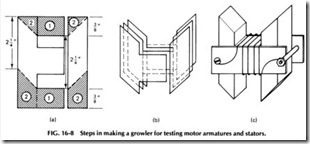
Laminations designed for use in making small transformers may be used to construct a growler for use in testing motor armatures or stators. The drawings in Fig. 16-8 show how the laminations may be trimmed and arranged for use in constructing a growler.
After the laminations are trimmed as shown by the dotted lines [Fig. 16-8(a)], they are stacked as shown in Fig. 16-8 (b), forming the letter H. Place the piece with the center bar attached on the work bench and then butt the I piece against the center bar as shown. The next two lamina tions are reversed so as to break joints. In other words, if the I piece is on the right for the first layer, it should be on the left for the next layer, and so on. Continue stacking the laminations alternately on first one side and then the other until you have a stack about 1in. high.
The laminations must now be bound together either with bolts or by using a bar clamp arrangement as shown in Fig. 16-8(c). Two pieces of fiber or wood about 3 in. long with a hole in each end may be used as a clamp. After the core is assembled, it should be carefully insulated. The part of the core which will come in contact with the wire should be
covered with a layer of varnished cambric or other insulating paper which may be wound around the core and over the fiber strips.
The winding of the growler consists of approximately 2000 turns of No. 34 AWG insulated wire. This wire should be carefully wound on the center part of the core as shown in Fig. 16-S(c). Terminals may be pro vided on the insulated clamp so that the ends of the coil may be attached to them, or the two clamping bolts may be used for the terminals.
Once the construction of the coil is completed, dip it in insulating varnish or else wind it with tape to protect the coil. This particular size is suited for testing small to medium armatures or stators. Other sizes may be cOnstructed using the same principle.
