Manual starters are characterized by the fact that the operator must go to the location of the starter to initiate any change of action. There are several different types of manual starters. Some look like a simple toggle switch with the addition of an overload heater. Others are operated by push buttons and may or may not be capable of providing low voltage protection.
Fractional Horsepower Single-Phase Starters
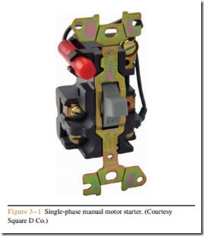
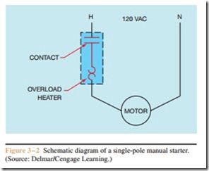
One of the simplest manual motor starters resembles a simple toggle switch with the addition of an overload heater (Figure 3–1). The toggle switch lever is mounted on the front of the starter and is used to control the on and off operation of the motor. In addition to being an on and off switch, the toggle switch also provides overload protection for the motor. An overload heater is connected in series with the motor (Figure 3–2). When current flows, the heater will produce heat in
proportion to the amount of motor current. If the heater is sized correctly, it will never get hot enough to open the circuit under normal operating conditions. If the motor should become overloaded, however, current will increase, causing a corresponding increase in heat production by the heater. If the heat becomes great enough, it will cause a mechanical mechanism to trip and open the switch contacts, disconnecting the motor from the power line. If the starter trips on overload, the switch lever will move to a center position. The starter must be reset before the motor can be restarted by mov- ing the lever to the full OFF position. This action is ba- sically the same as resetting a tripped circuit breaker. The starter shown in this example has only one line contact and is generally used to protect single-phase motors intended to operate on 120 volts.
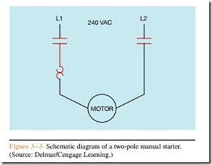
Starters that are intended to protect motors that operate on 240 volts should contain two load contacts (Figure 3–3). Although a starter that contains only one contact would be able to control the operation of a 240 volt motor, it could create a hazardous situation. If the motor were switched off and an electrician tried to disconnect the motor, one power line would still be connected directly to the motor. The National Electrical Code (NEC) requires that a disconnecting means open all ungrounded supply conductors to a motor.
Manual starters of this type are intended to control fractional horsepower motors only. Motors of 1 horse- power or less are considered fractional horsepower. Starters of this type are across-the-line starters. This means that they connect the motor directly to the power line. Some motors can draw up to 600% of rated full load current during starting. These starters generally do not contain large enough contacts to handle the current surge of multi-horsepower motors.
Another factor that should be taken into consideration when using a starter of this type is that it does not provide low voltage release. Most manual starters are strictly mechanical devices and do not contain an electrical coil. The contacts are mechanically opened and closed. This simply means that if the motor is in operation and the power fails, the motor will restart when the power is restored. This can be an advantage in some situations where the starter controls unattended devices such as pumps, fans, blowers, air conditioning, and refrigeration equipment. This feature saves the maintenance electrician from having to go around the plant and restart all the motors when power returns after a power failure.
However, this automatic restart feature can also be a disadvantage on equipment such as lathes, milling machines, saws, drill presses, and any other type of ma- chine that may have an operator present. The unexpected and sudden restart of a piece of equipment could be the source of injury.
Mounting
Mounting a fractional horsepower single-phase starter is generally very simple because it requires very little space. The compact design of this starter permits it to be mounted in a single gang switch or conduit box or directly onto a piece of machinery. The open type starter can be mounted in the wall and covered with a single gang switch cover plate. The ON and OFF markings on the switch lever make it appear to be a simple toggle switch.
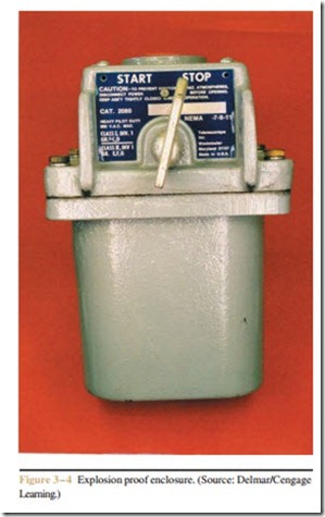
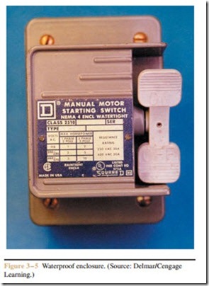
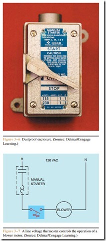
Like larger starters, fractional horsepower starters are available in different enclosures. Some are simple sheet metal and are intended to be mounted on the surface of a piece of machinery. If the starter is to be mounted in an area containing hazardous vapors or gasses, it may require an explosion proof enclosure (Figure 3–4). Areas that are subject to high moisture may require a waterproof enclosure (Figure 3–5). In areas that have a high concentration of flammable dust, the starter may be housed in a dustproof enclosure similar to the one shown in Figure 3–6.
Automatic Operation
It is sometimes necessary to combine the manual starter with other sensing devices to obtain the desired control. When using a sensing pilot device to directly control the operation of a motor, you must make sure
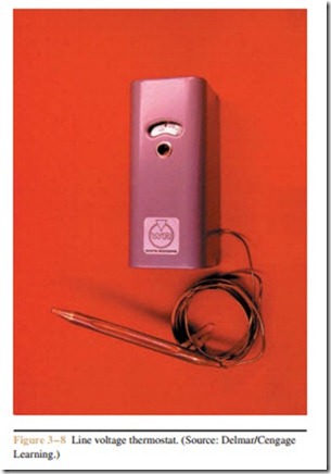
that the type of pilot device is equipped with contacts that can handle the rated current of the motor. These devices are generally referred to as “line voltage” de- vices. Line voltage devices have larger contacts than those sensing pilot devices intended for use in a motor control circuit that employs a magnetic motor starter. The smaller pilot devices intended for use with mag- netic motor starters have contacts that are typically rated from 1 to 3 amperes. Line voltage devices may have contacts rated for 15 to 20 amperes. A good ex- ample of how a line voltage sensing device can be used in conjunction with the manual starter is shown in Figure 3–7. In this circuit, a line voltage thermostat is used to control the operation of a blower motor. When the temperature rises to a sufficient level, the thermo- stat contacts close, connecting the motor directly to the power line if the manual starter contacts are closed. When the temperature drops, the thermostat contact opens and turns off the motor. A line voltage thermo- stat is shown in Figure 3–8.
Another circuit that permits the motor to be con- trolled either manually or automatically is shown in
In the Manual position, the pump is controlled by turning the starter on or off. An amber pilot light is used to indicate when the manual starter contacts are closed, or turned on. If the manual-automatic switch is moved to the Automatic position (Figure 3–10), a line voltage float switch controls the operation of the pump motor. If the water in the tank drops to a low enough level, the float switch contact closes and starts the pump motor. If water rises to a high enough level, the float switch contact will open and disconnect the pump motor from the line.
Related posts:
Incoming search terms:
- fractional horse power motor can be connected to the supply without starter why?
- why fractional horsepower motors can be connected to the supply without starter
- fractional horse power motors can be connected to the supply without starter why?
- why fractional horsepower motor can be connected to the supply without starter Why ?
- why fractional horse power motors can be connectedto the supply without starter
- why fractional horse power motors can be connected to the supply without starter
- manual starter experiences an overload an overload trips a mechanical latch causing the contacts to open
- Manual Starter
- frctiinal horse power motors can be cnnected to the dupply without starter why?
- fractional horsepower motor can be connected to the supply without starter
- fractional horse power motor can be connected to thw supply without starter and why
- fractional horse power motor can be connected to the supply without starter
- 3 HP motor single phase starter manual
