Objectives
After studying this unit, the student will be able to:
• Discuss how the PN junction is produced
• Recognize the schematic symbol for a diode
• Discuss the differences between the conventional current flow theory and the electron flow theory
• Discuss how the diode operates in a circuit
• Identify the anode and cathode leads of a diode
• Properly connect the diode in an electric circuit
• Discuss the differences between a half-wave rectifier and a full-wave rectifier
Test the diode with an ohmmeter
Hundreds of different electronic devices have been produced since the invention of solid-state components. As stated previously, solid-state de vices are made by combining P-type and N-type materials. The device produced is determined by the number of layers of material used, the thick ness of the layers of material, and the manner in which the layers are joined.
It is not within the scope of this text to cover even a small portion of these devices. The devices that are covered have been selected because of their frequent use in industry as opposed to com munications or computers. These devices are pre sented in a straightforward, practical manner, and mathematical explanation is used only when nec essary.
The PN junction is often referred to as the diode. The diode is the simplest of all electronic devices. It is made by joining a piece of P-type material and a piece of N-type material, figure 3-1. The schematic symbol for a diode is shown in figure 3-2. The diode operates like an electric check valve in that it permits current to flow through it in only one direction. If the diode is to conduct current, it must be forward biased. The diode is forward biased only when a positive volt age is connected to the anode and a negative volt age is connected to the cathode. If the diode is reverse biased, the negative voltage connected to the anode and the positive voltage connected to the cathode, it will act like an open switch and no current will flow through the device.
When working with solid-state circuits, it is important to realize that circuits are often ex plained assuming conventional current flow as op posed to electron flow. The conventional current flow theory assumes that current flows from positive to negative, while the electron flow theory states that current flows from negative to positive. Although it has been known for many years that current flows from negative to positive, many electronic circuit explanations assume a positive to negative current flow. There are several reasons for this assump tion. One reason is that ground is generally nega tive and is considered to be 0 volts in an electronic circuit. Any voltage above, or greater, than ground is positive. Most people find it is easier to think of something flowing downhill or from some point above to some point below. Another reason is that all of the arrows in an electronic schematic are pointed in the direction of conventional cur rent flow. The diode shown in figure 3-2 is for ward biased only when a positive voltage is ap plied to the anode and a negative voltage is applied to the cathode. If the conventional current flow theory is used, current will flow in the direction the arrow is pointing. If the electron theory of cur rent flow is used, current must flow against the arrow.
A common example of the use of the conven tional current flow theory is the electrical system of an automobile. Most automobiles use a negative ground system, which means that the negative ter minal of the battery is grounded. The positive ter minal of the battery is considered to be the “hot” terminal, and it is generally assumed that current flows from the “hot” terminal to ground.
The diode can be tested with an ohmmeter (see Procedure 1 in the Appendix). When the leads of an ohmmeter are connected to a diode, the diode should show continuity in only one di rection. For example, assume that when the leads of an ohmmeter are connected to a diode, it shows continuity. If the leads are reversed, the ohmme ter should indicate an open circuit. If the diode shows continuity in both directions, it is shorted. If the ohmmeter indicates no continuity in either direction, the diode is open.
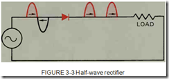
The diode can be used to perform many jobs, but it is most commonly used in industry to con struct a rectifier. A rectifier is a device that changes, or converts, ac voltage into de voltage. The simplest type of rectifier is the half-wave rec tifier, figure 3-3. The half-wave rectifier can be constructed using only one diode. It gets its name from the fact that it will rectify only half of the ac waveform applied to it. When the voltage applied to the anode is positive, the diode is forward biased and current flows through the diode, the load resistor, and back to the power supply. When the voltage applied to the anode is negative, the diode is reverse biased and no current will flow. Since the diode permits current to flow through the load resistor in only one direction, the current is direct current.
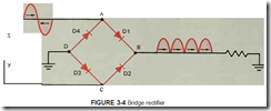
Diodes can be connected to produce full-wave rectification, which means that both halves of the ac waveform are made to flow in the same direc tion. One type of full-wave rectifier is the bridge rectifier, figure 3-4. Notice that four diodes are re quired to construct the bridge rectifier.
To understand the operation of the bridge rectifier shown in figure 3-4, assume that point X of the ac source is positive and point Y is negative. Current flows to point A of the rectifier. At point A, diode D4 is reverse biased and Dl is forward biased; therefore, the current flows through diode Dl to point B of the rectifier. At point B, diode D2 is reverse biased, so the current must flow through the load resistor to ground. The current returns through ground to point D of the rectifier. At point D, both diodes D3 and D4 arc forward biased, but current will not flow from positive to positive. Therefore, the current flows through diode D3 to point C of the bridge, and then to point Y of the ac source, which is negative at this time. Since current flowed through the load resis tor during this half cycle, a voltage developed across the resistor.
Now assume that point Y of the ac source is positive and point X is negative. Current flows from point Y to point C of the rectifier. At point C, diode D3 is reverse biased and diode D2 is for ward biased. The current flows through diode D2 to point B of the rectifier. At point B, diode Dl is reverse biased, so the current must flow through the load resistor to ground. The current flows from ground to point D of the bridge. At point D, both diodes D3 and D4 are forward biased. Since current will not flow from positive to positive, the current flows through diode D4 to point A of the bridge and then to point X which is now negative. Current flowed through the load resistor during this half cycle, so a voltage developed across the load resistor. Notice that the current flowed in the same direction through the resistor during both half cycles.
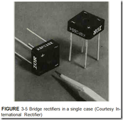
Bridge rectifiers in single cases are shown in figure 3-5.
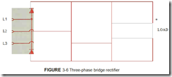
In industry three-phase power is used more often than single-phase power. Six diodes can be connected to form a three-phase bridge rectifier that will change three-phase ac voltage into de voltage, figure 3-6.
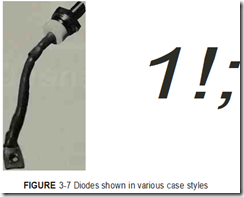
When the diode is to be connected in a cir cuit, there must be some means of identifying the anode and the cathode . Diodes are made in differ ent case styles, as shown in figure 3-7, so there are different methods of identifying the leads. Large stud mounted diodes often have the diode symbol printed on the case to show proper lead identifi cation. Small plastic case diodes often have a line or band around one end of the case, figure 3-8. This line or band represents the line in front of the arrow on the schematic symbol of the diode. An ohmmeter can always be used to determine the proper lead identification if the polarity of the ohmmeter leads is known. The positive lead of the ohmmeter must be connected to the anode to make the diode forward biased.
REVIEW QUESTIONS
1. The PN junction is more commonly known as the _
2. Draw the schematic symbol for a diode.
3. Explain how a diode operates.
4. Explain the difference between the conventional current flow theory and the electron flow theory.
5. Explain the difference between a half-wave rectifier and a full-wave rectifier.
6. Explain how to test a diode with an ohmmeter.


