Thermocouples
THEORY
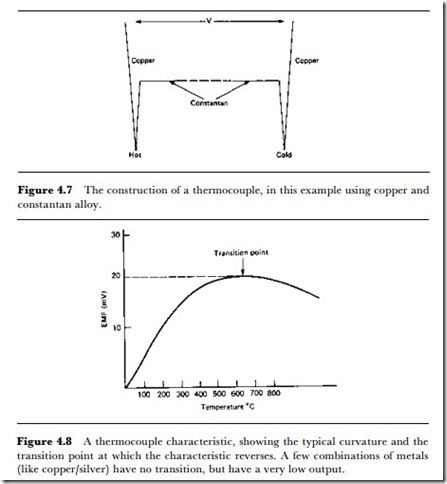
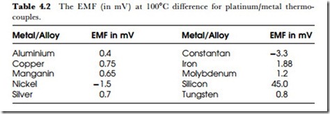
The thermocouple is frequently used as the sensing element in a thermal sensor or switch. The principle is that two dissimilar metals always have a (small) contact potential between them, and this contact potential changes as the temperature changes. The contact potential cannot be measured for a single connection (or junction), but when two junctions are in a circuit with the junctions at different temperatures, then a voltage of a few millivolts can be detected (Figure 4.7). This voltage will be zero if the junctions are at the same temperature, and will increase as the temperature of one junction relative to the other is changed until a peak is reached. The shape of the typical characteristic is shown in Figure 4.8, from which you can see
that the thermocouple is useful only over a limited range of temperature due to the non-linear shape of the characteristic and the reversal that takes place at temperatures higher than the turn-over point.
The thermocouple makes use of the Seebeck effect, and the theory of this leads to an equation for EMF:
where a, b and c are constants for the types of metals used in the thermocou- ple and () is the temperature difference between them. If the cold junction is held at 0oC, then the EMF equation becomes:
where a and (3 are measured constants for the pair of metals, and T is the temperature difference. For temperatures below the transition point a is usually small, so that the EMF is almost directly proportional to temperature difference.
• The Peltier effect, see later, is the reverse of the Seebeck effect.
• The Kelvin effect is much less well-known, and it concerns EMF generated in a conductor with no junctions. In such a conductor, a temperature difference between two different parts of the conductor will cause an EMF to be developed.
When an electric current flows through a conductor whose ends are maintained at different temperatures, heat is released at a rate approximately proportional to the product of the current and the temperature gradient.
• Any practicable circuit including a thermocouple will contain more than two junctions of differing metals, and the circuits have to be designed so that only the intended junctions are at different temperatures.
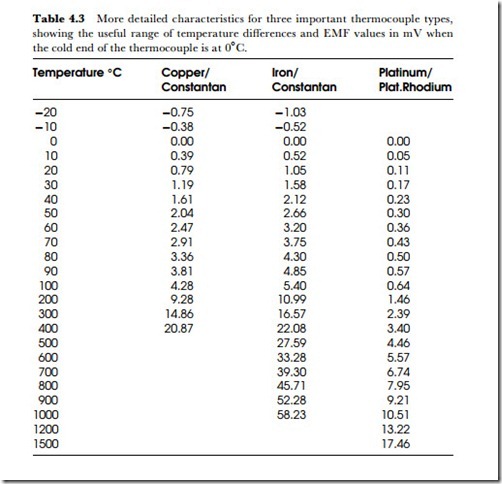
The output from a thermocouple is small, of the order of millivolts for a 10oC temperature difference, and Table 4.2 shows typical EMF values for metals and alloys, using platinum as the other metal of the couple. Table 4.3 shows values of EMF and temperature difference for three commonly
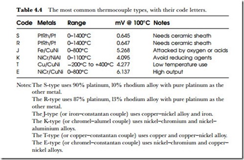
Table 4.3 More detailed characteristics for three important thermocouple types, showing the useful range of temperature differences and EMF values in mV when the cold end of the thermocouple is at 0oC.
used thermocouple materials. Of these, the copperjconstantan type is used mainly for the lower range of temperatures and the platinumjrhodium type for the higher temperatures. Because of the small voltage output, amplification is usually needed, unless the thermocouple is used for tem- perature measurement, together with a sensitive millivoltmeter. If the output of the thermocouple is required to drive anything more than a meter movement, then DC amplification will be needed, using an opera- tional amplifier or chopper amplifier (see Chapter 12). The type of amplifier that is used needs to be carefully selected, because good drift stability is necessary unless the device is recalibrated at frequent intervals. This makes the chopper type of amplifier preferable for most applications.
If an onjoff switching action is required, the thermocouple must be used along with a controller that uses a Schmitt trigger type of circuit which also permits adjustment of bias so that the switching temperature can be pre-set. The usual circuitry includes amplification, because the lower ranges of thermocouple outputs are comparable with the contact potentials (the same type of effect) in amplifier circuits, and attempting to use very small inputs for switching invariably leads to problems of low hysteresis and excessive sensitivity.
One particular advantage of thermocouples is that the sensing elements themselves are very small, allowing thermocouples to be inserted into very small spaces and to respond to rapidly changing temperatures. The electrical nature of the process means that the circuitry for reading the thermocouple output can be remote from the sensor itself. Note that thermocouple effects will be encountered wherever one metallic conductor meets another, so that temperature differences along circuit boards can also give rise to voltages that are comparable with the output from thermocouples. The form of construction of amplifiers for thermocouples is therefore important, and some form of zero setting is needed.
PRACTICAL USE
Thermocouples are very widely used industrially, making the thermocouple one of the most important of temperature sensors. Of the many possible combinations of metals that could be used for thermocouples, only a few are practical from the consideration of a reasonably linear scale and good resistance to high temperatures. Table 4.4 shows the most commonly used
types. These fall into two groups, the base metaL types such as iron- constantan and the nobLe metaL types such as platinum-rhodium-platinum. The noble metal (originally named because of their resistance to all known acids) thermocouples are required for the higher temperatures, but have lower output levels and require ceramic sheathing to avoid oxidation damage. Thermocouples that use iron as one wire require protection against rusting and against oxidizing atmospheres generally.
The differences between thermocouple measurements and those made by other means are not always well appreciated, however. A thermocouple measurement is always a differential measurement, measuring the tempera- ture difference between the cold or reference junction and the hot or measuring junction. When neither of the metals used in the thermocouple is the same as that used for the connecting cable, there will be two sets of junctions. Tables for thermocouple use are always made up in the assumption that the reference junction will be at 0oC. In industrial use this is very seldom true, and some form of compensation has to be used so that the output readings can be adjusted for the true temperature of the reference junction(s).
The usual method is coLd-junction compensation incorporated into the amplifierjoutput portion of the instrument. A metal coil or a thermistor is used to sense the temperature at the reference junction or junctions, and the output from this sensor is used in an adding stage within the instrument to correct for the effect. This is most easily done in microprocessor-con- trolled equipment by using a table of correction values held in a ROM, but older analogue methods using an adding stage have been satisfactory in the past.
• Note that these methods apply a correction based on the cable that is supplied with the instrument. Changing to a different cable material (for example, extending the thermocouple connecting cable with copper cable) can make the built-in correction factor false, since two new junctions have now been added.
For precise measurements, although thermocouples are not ideal for such applications, it is more usual to have the reference junction(s) held in temperature reference units. The ice-point form of the reference unit is held at 0oC using Peltier cooling junctions (the reverse of the thermocouple effect) and precise sensors for the reference temperature, such as the bellows type which makes use of the expansion which occurs as water changes to ice. The traditional way of establishing the zero reference point was to use a vacuum flask filled with a mixture of ice and water, but this can cause large discrepancies unless used carefully.
The main objection is that ice which has been taken from a freezer will often be at 15oC or lower, and the water around it at around +5oC, so that the reference junction will quite certainly be at the wrong temperature and also at a temperature which will change considerably. The water-ice mixture is suitable if the water is demineralized (and the ice made from similar water), the ice is crushed, not in lumps, the ice has been in contact with the water for a considerable time and is constantly stirred, and the reference junction is not in contact with the ice.
The hotbox reference system uses a solid aluminium block with a drilled cavity into which the reference junction is placed. The block temperature is maintained constant, usually at a temperature well above ambient in the region of 55-65oC. The temperature of the block is raised quickly to its steady level by a heater which switches off when the temperature approaches the controlled level. From then on, the temperature is con- trolled by a thermistor and a small heating element operating in a loop with an amplifier. The instrumentation for the thermocouple must include circuitry that will correct the readings for the raised temperature of the reference junction by adding a small voltage to the output of the thermo- couple.
• Another method, which is a passive system, consists of embedding the reference junction in a metal block that is well insulated, so that its tem- perature changes only very slowly. Another sensor in the block is connected to the instrumentation and generates the correction signal for the reference junction temperature.
The connections between the thermocouple and the reading system are important, as has been mentioned. When the distance between the thermo- couple and the measuring instrument is considerable, extension or compensating cables should be used to connect these two. The difference between these two is that extension leads use the same materials as the thermo- couples, and can be used at the same temperatures. Compensating cables use low-cost metals and can be used in ambient temperatures up to about 80oC only. The compensating cables must be matched to the type of thermocouple being used, and both extension and compensating cables must be connected in the correct polarity.
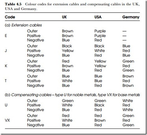
Cables made to the British standard (BS 1843:1952) all use codings in which the negative lead is blue, but the US ANSI cables use red for negative and the German DIN specifications use red for positive. In each case, the other colour is used for the opposite polarity (Table 4.5). Because the colours are not internationally standardized, it is important to know the country of origin of thermocouple extension or compensating cables and the market for which they were intended (cables of German origin might have been manufactured for sale in the USA and carry the ANSI colour coding).
Whatever type of thermocouple is used, many applications will require the measuring junction to be sheathed to prevent contact with such materials as molten metals, hot or corrosive gases and corrosive liquids. For some applications, the junction can be allowed to protrude outside the sheathing if a fast response is needed, particularly for gas temperature
measurements, although this is not permissible if the gas is corrosive. The alternatives are to use the isolated type of sheathings, in which the junction is totally insulated electrically, or the grounded type, in which the junction makes contact with the sheathing. The latter type also gives good protection against corrosive materials, but with a considerably faster response.
Both the fully sheathed types must be used in high-pressure environments. Table 4.6 lists materials commonly used for sheathing thermocouples for industrial uses. The 27% chrome alloy is the most widely used type for low-temperature molten metal bath measurements, particularly for lead and zinc alloys. Stainless steel is better than nickel alloys in atmospheres that contain oxides of sulphur (exhaust gases from burning coal or oil, for example), and the ceramic materials must be used for sheathing noble metal thermocouples.
