Motor Maintenance
To ensure the best operation .. a systematic motor inspection should be made at regular intervals, the frequency depending on the type of service and operating conditions. There are five important procedures that should be followed in the proper maintenance of motors. They are:
1. Schedule the shutdown time of machines and notify the electrical department whenever a machine is, or will be, available for mechanical work so that the electric equipment can be checked simultaneously.
2. Build up and maintain a reserve of units, parts, and subassemblies so that quick changes can be made.
3. Keep spare units and renewal parts clean, dry, and in good order for quick application.
4. Keep records of troubles and remedies as a means for running down chronic cases and finding the causes.
5. Make inspections as regularly and thoroughly as circumstances will permit.
Check the installations of new motors, controls, and replacement after putting them into service. Some maladjustment may be discovered that might cause considerable trouble if the scheduled inspection date is far ahead. Dampness or excessive temperature and humidity will, in time, deteriorate the insulation of the motor windings, resulting in grounds or short circuits. Particular care must be given to frequent inspection, maintenance, and repair of motors operating under such adverse conditions.
Keep a card file of the equipment. Set up a schedule of inspection that can be met with a reasonable man-hour demand. Find out what an increased department output will mean to the motors, and be sure that the electrical loads are not stepped up to a point where failures will curtail production.
All types of motors have many elements in common for which maintenance work is fairly uniform. Insulated windings, brushes, collector rings, commutators, and bearings are treated independently of the machines in which they are used. The same is true of disassembly and assembly, and also of external inspection.
INSPECTION
Advance notice of trouble is often provided by inspection. Careful inspections by a conscientious and observant man are much more valuable than careless routine inspections at more frequent intervals. Since a lubrication man should visit each motor at fairly regular intervals, he should be able to check for noise, heat, changes in surroundings, or other abnormal conditions. Regular and more detailed inspections can be scheduled, but a system should be established that can be continued in a consistent manner.
The frequency of inspections that should be made will vary between plants and between departments in a given plant. It will also vary with the types of motors involved. While inspections are normally scheduled for definite intervals, the intervals are only relative and, in many cases, can be somewhat extended, depending on local conditions.
Weekly Inspection
Sleeve Bearings-If an oil gauge is used on sleeve-bearing motors, check the oil level and fill to the line, if necessary. Where the journal size is less than two inches, stop the motor before attempting to check the oil level.
For special lubricating systems, such as wool-packed, forced flood, and disk, refer to the manufacturer’s recommendations.
Add oil to the bearing housing if needed, but only while the motor is stopped. Check to see if oil is creeping along the shaft toward the windings. If oil creep is present, report the condition immediately.
Ball or Roller Bearings-Feel the bearing housing for evidence of vibration, any unusual noise, or excessive temperature. Inspect for creepage of grease on inside of motor.
Brushes, Commutators, and Rings-Check for sparking at the brushes. If the motor is on a cycle duty, observe it through several cycles. Note the color and condition of the commutator or rings. Inspect all brushes for wear, and check pigtail connections for looseness. Check commutators or rings for burned spots or roughness. Clean the surfaces with a commutator cleaning stick.
Rotors and Armatures-Check the air gap on sleeve-bearing motors, especially if recently overhauled. If new bearings have been installed, make sure that the average air gap is within 10% if the gap is normally less than 20 mils (0.5mm). See if the air passages through the punchings are clogged with foreign matter. If needed, clean by vacuuming or mild blowing. Make sure the machine is stopped and the electricity off. Wipe off the dust with a dry cloth. Check for moisture and the accumulation of water in the bottom of the frame. See if any oil or grease has worked its way up to the rotor or armature windings. If so, clean with carbon tetrachloride in a well-ventilated room.
Mechanical Condition-Check belts for suitable slack and surface condition. Look at all gears for signs of uneven wear. Check flexible couplings. If they are properly lined up, there will be no noise or evidence of excessive use of the flexible factor. See if chains clear the housings. Check the chain lubrication, especially for excess grease and oil in the bottom of the housing. See if sprockets show even wear across the teeth. Check the motor starting to see that the motor comes up to proper speed each time power is applied. Report any abnormal action for a control checkup.
Monthly Inspection
Windings-Check shunt, series, and commutating fields for tight ness. Try to move the field spools on the poles; drying out may cause some play. Check the machine cable connections for tightness.
Brushes-Check the brushes in their holders for fit and free play. Check the brush-spring pressure. Tighten the brush studs to take up any slack caused by the washers drying out. Be sure the studs are not displaced on de units. Replace all brushes that are worn down almost to the brush rivet. Examine the brush faces for chipped toes or heels, and for heat cracks. Replace any that are damaged.
Commutators-Examine commutator surfaces for high bars and high mica, or for evidence of scratches or roughness. See that the risers are clean and have not been damaged in any way.
Ball or Roller Bearings-On hard-driven 24-hour-service motors, purge out all old grease through the drain hole and apply new grease. Check to make sure that grease or oil is not leaking out of the bearing housing. If any leakage is present, correct the condition before contin uing to operate.
Sleeve Bearings-Look for bearing wear, including end play at the bearing surf aces. Clean out oil wells if there is evidence of dirt or sludge. Flush well with lighter oil before refilling.
Enclosed Gears-Open the drain plug and check the oil flow for the presence of metal scale, sand, or water. If the condition of the oil is bad, drain, flush and refill as directed. Rock the rotor to see if the slack or backlash is increasing.
Couplings and Drive Units-Note if the belt-tightening adjustment is all taken up. Shorten the belt if this condition exists. See if the belt runs steadily and close to the motor edge of the pulley. Chains should be checked for evidence of wear and stretch. Clean the inside of chain housings. Check the chain-lubricating system. Note the incline of slanting bases to make sure they do not cause the oil rings to rub on the housing.
Loads-Check loads for changed conditions, bad adjustment, poor handling, or control trouble.
Yearly Inspection
Windings-Check the insulation resistance. Also check the insula tion surfaces for dry cracks and other evidence of the need for coatings of insulating material. Clean all surfaces and ventilation passages thoroughly if an inspection shows an accumulation of dust. Check for moisture, mold, or water standing in motors to see if varnishing and baking are needed after drying out the windings.
Air Gaps and Bearings-Check all air gaps to make sure that the average reading is within 10%, provided the reading should be less than 20 mils or (0.5mm). All bearings should be thoroughly checked and the defective ones replaced. Waste-packed and wick-oiled bearings should have the waste or wicks renewed if they have become glazed or filled with metal or dirt. See that the new waste bears snugly against the shaft.
Squirrel-Cage Rotors-Check for broken or loose bars and evi dence of local heating. If fan blades are not cast in place, check for loose blades. Look for marks on the rotor surface indicating foreign matter in the air gap, or worn bearings.
Wound Rotors-Thoroughly clean around the collector rings, washers, and connections. Tighten the connections if necessary. If the rings are rough, spotted, or eccentric, send them to the repair shop for refinishing. See that all top sticks or wedges are tight. Thoroughly clean all air passages . Look for oil or grease creepage along the shaft, checking back to the bearing. Check the commutator for surface condition, high bars, high mica, and eccentricity.
Mechanical Condition-Check belts or chains for possible need of replacement. Do not wait for them to break during a production rush. Clean the inside and outside of the frames and end belts. Turn the rotor by hand to locate misalignment, a sprung shaft, or rubbing. If the motor is connected to a machine, check the turning with a lever to see if the machine imposes an excessive friction load.
Loads-Read the load on the motor with instruments at no load, full load, or through a complete cycle, as a check on the mechanical condition of the driven machine.
INITIAL MOTOR STARTING
Prior to starting a motor for the first time, observe the following:
1. Dry out all moisture. If the motor has been exposed to a moist atmosphere for long periods while in transit or storage (or has remained idle for a long period after being installed in a moist atmosphere), it should be dried out thoroughly before being placed in service. If possible, place the motor in an oven and bake at a temperature not exceeding 85°C ( 185°F). Fair results can be obtained by enclosing the motor with canvas or other covering, inserting heating units or incandescent lamps to raise the temper ature, and leaving a hole at the top of the enclosure to permit the escape of moisture. The motor may also be dried out by passing a current at low voltage (motor at rest) through the field windings sufficient to raise the temperature to not over 85°C ( 185°F). Increase the temperature gradually to this value, keeping the temperature of the entire winding as nearly uniform as possible.
2. See that the voltage on the motor and control name-plates corre sponds with that of the power supply.
3. Check all connections to the motor and control with the wiring diagrams.
4. Make sure that the drain plugs are tight and that the bearings are lubricated properly.
5. If oil-ring bearings are used, make sure that the oil rings turn freely.
6. Remove all the external load, if possible, and turn the armature by hand to see that it rotates freely.
7. Before putting the motor without load long enough localized heating.
DETERMINATION OF BELT SIZES
For a given condition, the minimum belt width is determined by the horsepower to be transmitted and by the speed of the belt. The rules are as follows:
Rule 1-A single belt 1 in. (25.4mm) wide, running at 800ft.
(243.84 m) per minute, will deliver approximately 1 horsepower (.746 k (up to about 4000 r/min).
Rule 2-A double belt 1 in. (25.4mm) wide, running at 500ft. per minute (152.4m) will deliver approximately 1 horsepower(. 746 k (up to about 4000 r/min).
These rules give wide margins of safety in ordinary power transmis sion when the speed of the belt does not exceed 4000 feet per minute (1.22km). Above this speed, the centrifugal effects due to the belt weight begin to be rather appreciable and should therefore be included.
For heavy transmission and speeds exceeding 4000 feet per minute ( 1.22km) the foregoing rules should be checked against the manufac
turer’s recommendations. It is more convenient, for calculation pur poses, to express the rules just given in algebraic form. Thus, for single belts:
where,
Bw is the belt width in inches,
V is the belt speed in feet per minute,
hp is the horsepower transmitted.
Similarily, for double belts:
Note: If metric measurement is used you will have to develop a different formula.
Example- What size of double belt is required to transmit 50 horsepower at a belt speed of 4000 feet per minute?
Solution-According to the formula, the belt width is:
Example-If a single belt is used in the previous example, what will be its size?
. Solution-Substituting numerical values, the width of the single belt is :
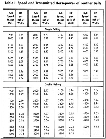
The ratio 10 / 6.25 = 1.6 indicates that a double belt is not considered to be twice as effective as a single belt, but only 1.6 times as effective. A useful listing giving the horsepower per inch of width transmitted by leather belts is given in Table 1. To obtain the horse power transmitted by belts of any width, multiply the figure shown for the given belt speed by the width of the belt used. Thus, for example, if the belt speed is 4000 feet per minute ( 1.22km) and the width of the double belt is 6-1/4 in., multiply the figure corresponding to a speed of 4000 feet per minute by the width of the belt to obtain the horsepower transmitted. Thus, 6.25 x 7.94 = 49-5/8, or approximately 50 hp Again, if the horsepower to be transmitted and the belt speed in feet per minute are known, divide the figure shown for a given belt speed by the horsepower to be transmitted to obtain the belt width.
Example-An electric motor rated at 10 hp has a full-load speed of 1150 r/min and a pulley diameter of 8 in., and is to drive a drilling machine by means of a belt. What width of single belt is required?
Solution-Since the speed of the motor is 1150 r/min and its pulley diameter is 8 in., it is necessary to first find the belt speed in feet per minute. This will conveniently be found by remembering that the belt speed (V) is equal to π X D X N,
where:
π is 3 . 1416,
D is the pulley diameter in feet,
N is the rpm of motor
By consulting Table 1, the figure corresponding to a belt speed of 2410 is most nearly 3.33. By dividing this figure by the horsepower transmitted to the belt, the width of the belt is finally obtained thus;
BELT-DRIVE ARRANGEMENTS
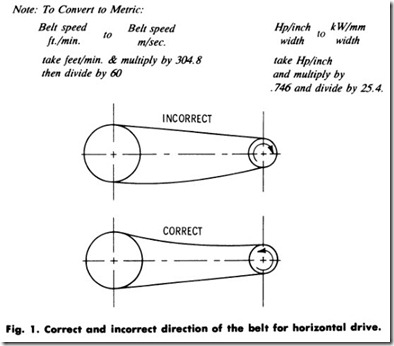
Whenever conditions permit, horizontal drives should be used for belts. The proper procedure is to arrange the belt as shown in Fig. 1-that is, with the lower side of the belt driving. The sag of the upper side of the belt tends to increase the arc of contact on the pulley. This sag should be about 1-1/2 inches for every 10 feet of center distance between the shafts. If too loose, the belt will have an unsteady flapping motion which will injure both the belt and the machinery. If too tight, the bearings will be put under a severe strain, resulting in a probable early failure, and the belt will be quickly destroyed.
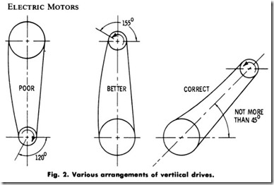
Vertical drives arranged as shown in Fig. 2 should be avoided whenever possible. This is particularly true where the lower pulley is the smaller. The reason why vertical drives prove less satisfactory than horizontal drives is that, in the vertical drive, the effective tension and arc contact are substantially reduced, and as a result the slip will increase in extreme cases to the point where the normal load cannot be carried. Fig. 2 illustrates how, in the best arrangement, the angle should not exceed 45 degrees.
In group drives where several belts transmit power from a line shaft, it is advantageous to locate the drive shaft so that the bearing pressure can be equalized and reduced by alternating the direction of the drives, first on one side and then on the other.
ALIGNMENT
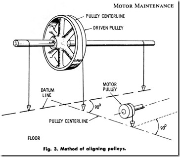
After the motor has been properly located and the right kind of mounting has been provided, the next step is to align the machine with its drive. The tools usually employed for alignment of machinery or line shafting are the square, plumb bob, and level. Fig. 3 shows a simple and easy method of aligning a motor pulley with the driven pulley. First, the crown or center line of the pulleys must be on the same center line, and second, the motor shaft must be parallel to the driven shaft.
By using a plumb bob and drawing a datum line on the floor, a base of operation is established. Next, drop a plumb line from the center of the driven pulley to the floor. With a square, draw a line perpendicular to the datum line. Next, drop a plumb line from the center of the motor pulley and move the motor up or back until the plumb bob rests on the center line of the driven pulley. From the pulley center line, perpen diculars may be drawn through the centers of the holes in the motor feet. A level should be used to see that the line shafting is level. If it is not, then the motor feet must be shimmed up so that the motor shaft and the line shaft will be “out of level” the same amount. Chain drives may be aligned in a similar manner.
With belt drives, a sliding base is nearly always used to allow for belt adjustment. Use the following procedure when aligning two pulleys:
1 . Place the motor on the baC)e so that there will be an equal amount of adjustment in either direction, and firmly fasten the motor to the base by means of the four hold-down bolts.
2 . Mount the motor pulley on the motor shaft.
3 . Locate the base and motor in the approximate final position, as determined by the length of the belt.
4 . Stretch a string from the face of the driven pulley toward the face of the motor pulley.
5 . Parallel the face of the motor pulley with this string.
6 . Using a scratch pin, mark the end positions of the sliding base.
7 . Extend these lines.
8 . Move the base and motor away from the string an amount equal to one-half the difference in face width of the two pulleys. Use the two extended lines as a guide to keep the base in its proper position.
9 . The belt should now be placed on the pulleys to see if it operates satisfactorily. If it does not, the base may be shifted slightly until proper operation is obtained.
1 0 . Finally, firmly fasten the base to the floor, ceiling, or side walls by means of lag screws or bolts.
BELT MAINTENANCE
It is of paramount importance that a proper maintenance schedule be observed. This consists of numerous details, the most important of which are:
1. Keeping belts tight,
2. Taking up the slack of belts,
3. Running in new belts,
4. Cleaning dirty belts,
5. Dressing belts,
6. Maintenance of belt guards.
In locations where idlers or tension-base drives are employed, the tightness of the belts is automatically adjusted to a desired value. Because of the absence of the necessary space requirements, however, this method is not always feasible, and the surplus length will have to be removed at certain intervals of time. Some belts stretch more than others under similar conditions and loads. Temperature and humidity are two factors which greatly influence belt tension. Locations of high humidity and moisture are known to cause a belt to expand more quickly.
After the elastic limit of a leather belt is reached, it may be stretched to the breaking point without becoming any tighter. The friction increases with the pressure, and the more elastic the surface, the greater the friction. To obtain the greatest amount of power from leather belts, the pulleys should also be covered with leather-this will allow the belts to run very slackly and give more wear. The leather in a belt should be pliable, of fine close fiber, solid in appearance, and have a smooth, polished surface.
Belts derive their power to transmit motion from the friction between the surface of the belt and the surface of the pulley, and from nothing else. The thickness as well as the width of belts must always be considered. Consequently, a double belt must be used where it is necessary to transmit a greater power than possible with a single belt. To increase the driving power of a belt, larger pulleys may be used, thus increasing the speed of the belt. This can often be done to advantage, provided that the belt speed is not carried above the safe limit.
DIRECTION OF ROTATION
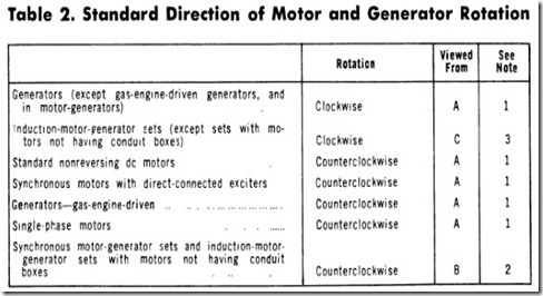
The rules in Table 2 govern the standard direction of rotation of generators and motors. In all cases, the observer will stand facing the designated end of the machine and in line with the shaft.
Note l. End A. The direction of rotation of standard motors and genera tors will be determined by viewing the end opposite the driven end of generators, and opposite the driving end of motors.
Note 2. End B. The direction of rotation of synchronous-motor-generator sets, induction-motor-generator sets with motors not having conduit boxes, and frequency changers, will be determined by the direction of rotation of the driving motor. When there are one or more generators on each end of the driving motor, the direction of rotation will be determined by viewing the motor from the connection end of the stator coils.
Note 3. End C The direction of rotation of induction-motor-generator sets will be determined by that of the generator. When there are one or more generators on each end of the driving motor, the direction will be determined by viewing the set from the end which places the conduit boxes on the left-hand side.
Polyphase induction motors, except certain high-speed motors equipped with unidirectional fans, are suitable for either direction of rotation of which can be reversed by interchanging any two leads. High-speed motors with unidirec tional fans must be ordered for the desired direction of rotation.
SUMMARY
Motor maintenance should be performed on a systematic schedule to minimize loss of down time. Adequate spare parts should be stocked for all motors and a record of troubles and cures maintained. Inspections should be made as regularly and thoroughly as circumstances permit.
Care should be taken when starting a new motor for the first time. It should be dry and the bearings properly lubricated. The armature should be turned by hand to make sure it rotates freely. All electrical connec tions should be double-checked. If possible, run the motor without load long enough to determine that no unusual localized heating is occurring.
Correct belt sizes are important to ensure proper operation of the equipment. Determine the correct type and size of belt by consulting the manufacturer’s instructions or by calculations by means of one of the formulas listed. Belts must be properly aligned to prevent excessive wear, loss of power, and premature failure. A regular maintenance schedule for belts should also be followed.
REVIEW QUESTIONS
I. List five important procedures that should be followed for the proper maintenance of motors.
2. List five points that should be checked before placing a new motor in operation.
3. What size of double belt will be required to transmit 25 horsepower at a belt speed of 3000 feet per minute?
4. What characteristic of a leather belt must be especially considered when it is to be installed in a location where the humidity is high?
5. What is the standard direction of rotation of single-phase motors?
6. What size belt will be required to transmit 18.56 kW at a belt speed of 15.24 m/sec?


