NAND Gate
A NAND gate is a combination of an inverter and an AND gate. It is called a NAND gate from the NOT- AND function it performs. The NAND gate is the most commonly used logic function. This is because it can be used to construct an AND gate, OR gate, inverter, or any combination of these functions.
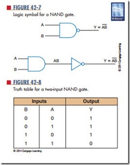
The logic symbol for a NAND gate is shown in Figure 42-7. Also shown is its equivalency to an AND gate and an inverter. The bubble on the output end of the symbol means to invert the AND function.
Figure 42-8 shows the truth table for a two-input NAND gate. Notice that the output of the NAND gate
is the complement of the output of an AND gate. Any 0 in the input yields a 1 output.
The algebraic formula for NAND-gate output is Y 5 AB, where Y is the output and A and B are the inputs. NAND gates are available with two, three, four, eight, and thirteen inputs.
NAND gates are the most widely available gates on the market. The availability and flexibility of the NAND gate allows it to be used for other types of gates. Figure 42-9 shows how a two-input NAND gate can be used to generate other logic functions.
Questions
1. What is a NAND gate?
2. Why is the NAND gate so often used in circuits?
3. Draw the logic symbol used to represent a NAND gate.
4. What is the algebraic expression for a NAND gate?
5. Develop a truth table for a three-input NAND gate.
