THREE-PHASE DRIVE SYSTEMS FOR DC MOTORS
For dc motors larger than about 10 hp, a three-phase drive system is superior to
a single-phase system. This is because a three-phase system provides more pulsations
of armature voltage per cycle of the ac line and thus gives greater average
armature current flow.
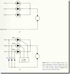
The simplest possible three-phase drive system is illustrated in Fig. 15-7(a).
Although this system gives only half-wave control, it is capable of keeping current
flowing through the armature continually. It can do this because when any one
phase goes negative, at least one of the other phases is bound to be positive. If a
certain phase is driving the armature, at the instant it reverses polarity, one of the
other two phases is ready to take over. Thus it is possible to keep armature current
flowing continually.
If no neutral fourth wire is available, three-phase half-wave control can be
accomplished by the addition of three rectifier diodes, as shown in Fig. 15-7(b).
During the time that line voltage AB is driving the armature, the flow path is down
line A, through SCRy4, through the armature, and through Dg into line B. When
line voltage BC is driving the armature, the armature current passes through SCRS
and D( . At the instant that line voltage CA is driving the armature, current passes
through SCRC, through the armature, and back into line A through diode D^.
AN EXAMPLE OF A THREE-PHASE DRIVE SYSTEM
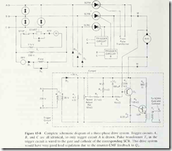
Figure 15-8 shows the complete schematic diagram of a three-phase drive system.
The 230-V, three-phase power is brought in at the upper left in that figure. Thyrectors
are installed across each of the three phases to protect the solid-state drive
circuits from high-voltage transient surges which may appear on the power lines.
A thyrector acts like two zener diodes connected back to back. If any momentary
voltage surge appears which exceeds the breakdown voltage of the thyrector, the
thyrector shorts out the excess. That is, the thyrector acts like a zener diode in
that it will allow only a certain amount of voltage to appear across its terminals.
If a greater voltage tries to appear, the thyrector becomes a short circuit to any
amount of voltage in excess of its rating. In this example, with 230 V rms between
the ac power lines, the peak voltage is about 324 V. The thyrectors would be chosen
to have a breakdown voltage rating somewhat larger than the peak line voltage.
In this case they would probably have a rating of about 400 V.
The 230-V ac appearing between power lines B and C (V^, ) is half-wave
rectified by diode D, and applied to the motor field winding. Diode D,, called a
free-wheeling diode, allows the field winding current to continue flowing during
the negative half cycle of the Vgc voltage. When Vg^ enter s its negative half cycle,
the field winding induces a voltage which is positive on the right and negative on
the left. This induced voltage forward-biases D,, causing current to flow through
the loop comprised of the field winding and Dj in the same direction as before.
Relay RFF is a field-failure relay. Its job is to constantly monitor the current
in the field winding. Since it must sense current, rather than voltage, its coil is
comprised of just a few turns of relatively heavy wire. As long as the field current
is flowing. RFF will remain energized. If the field current is interrupted for any
reason, RFF drops out. If it does drop out, it causes all power to be removed from
the armature winding, as described below. This is necessary because a dc motor
can be destroyed if its armature remains powered up when there is no magnetic
field present. With no magnetic field present, the armature winding is incapable
of generating enough counter-EMF to limit the armature current to a safe value.
Under this condition, the armature current would quickly surge up to a destructive
level, thereby overheating and ruining the armature conductors and/or insulation.
Even if the armature winding could withstand the electrical strain, the rotor speed
would increase drastically, in a vain attempt to induce sufficient counter-EMF.
This drastic increase in rotational speed can cause mechanical destruction due to
overheated bearings or armature windings thrown out of their slots by centrifugal
force.
Transformer T, steps the 23()-V line voltage down to 115 V for use in the
START-STOP circuit. This is done to provide safety to the operators who use the
START and STOP pushbuttons. When the START button is depressed, motor
starter M will be energized, as long as RFF is energized. The auxiliary M contact
then seals in around the START button, allowing the START pushbutton to be
released. The main A/ contacts are in series with the motor armature itself; when
those contacts close, armature current can flow, and the motor can begin running.
The motor will stop whenever the M coil deenergizes. This will happen if the
N.C. STOP pushbutton is temporarily depressed or if the RFF contact opens.
In the speed control circuit proper, SCR4 controls armature current when
V^if is in its positive half cycle (past the 60° point). Diode Dg then carries the
armature current back to line B. During the interval when Vgc drives the armature,
the armature current flows through SCRB and D^- When Vca drives the armature,
current flows through SCRC and D.,. SCRA is triggered by TRIGGER CIRCUIT
A, SCRB is triggered by TRIGGER CIRCUIT B, and SCRC is triggered by
TRIGGER CIRCUIT C. All three SCRs are fired at approximately the same firing
delay angle within their respective conduction cycles. This is accomplished by
ganging the three control potentiometers together.
TRIGGER CIRCUITS A. B, and C are all identical. The schematic diagram
of TRIGGER CIRCUIT /I is the only one of the three which is drawn schematically
in Fig. 15-8.
Trigger circuit. In the upper left of the trigger circuit, transformer T, steps
V^n down to 20 V ac. The T^ output voltage is rectified by diode D, to provide a
28-V peak supply for the triggering circuitry. To understand the operation of the
rest of the trigger circuit, assume for a moment that the N.C. M contact has been
open for a while and that Cj is fully charged. We will return later to see what these
components do.
The base current of pnp transistor Q^ is set by the speed-adjust pot. The base
current flow path is down from the + 28-V supply, through the emitter-base junction
of (?,, through /?j and R2, and into the lO-kll pot. As the pot wiper is adjusted
downwards, the voltage available for driving the (?, base increases, and the base
current increases. As the pot wiper is moved up, Q, base current decreases. The
Qi base current determines the Q, collector current, which charges capacitor C^.
through R^. As we saw in Chapter 5, the faster C^ charges, the earlier V,, of the
UJT is reached, and the earlier the SCR fires.
This trigger circuit has built-in speed regulation (load regulation) also, just
like the circuits of Figs. 15-3 and 15-4. The regulation is provided by 220-kn resistor
/?7. Here is how it works.
Suppose that the speed-adjust pot has been adjusted to provide 2000 rpm at
a certain load torque. Recognize that the counter-EMF voltage developed by the
armature tends to reverse-bios the emitter-base junction of Q,. through R-,. The
reverse-bias tendency due to this circuit is overcome by the /?4-/?2-speed adjust pot
combination which keeps Q, turned on and conducting. If the torque load on the
motor shaft increases, the motor slows down a little bit, and the counter-EMF
decreases. This reduces the reverse-bias tendency through Rj. Therefore the Q^
base current increases a little bit, and the transistor is able to charge C^ faster.
Because of this, the UJT fires earlier, and the SCR fires earlier. This raises the
average voltage that the SCR applies to the armature, tending to correct the motor
speed.
Let us return now to consider the circuit comprised of C.. R,. and the N.C.
contact of M. The purpose of this circuit is to accelerate the motor up to speed
slowly when it is first started. It does this by limiting the armature current for a
certain amount of time after the starter is energized. Prior to starter M being
energized, the N.C. M contact is closed and is holding capacitor C; discharged.
There is thus a short circuit across the path consisting of R^ and the Qi base-emitter
junction. Q^ is held cut-OFF at this time.
When the N.C. M contact opens as the motor starter energizes, C; begins
charging through resistor /?, and the speed-adjust pot. As Ct charges, it begins
acting more and more like an open circuit. As this takes place, the Q, base current
slowly builds up to the steady-state value determined by the pot setting. Until that
steady-state value is reached, the firing of the UJT and SCR is delayed past the
normal firing instant. In this manner the armature current is temporarily retarded
for a while after the starter energizes. Therefore the motor accelerates slowly to
its set speed, and the great initial inrush of armature current is avoided.
