FIELDBUSES
12.3.1 Fieldbus systems
Fieldbuses were developed to replace the HART technology, discussed in section 12.2, in which centralized electronic instrumentation employs both 4 20 mA analog signals and a global digital communication standard. These two communication channels, analog and digital, simultaneously transmit through cables between hundreds of field devices and a central controller, thus enormous lengths of special cables may be needed.
Fieldbuses were expected to offer cost savings due to reduced wiring and terminations, short engineering and configuration times, fast loop-check-out and commissioning procedures and increased plant uptime resulting from advanced and fast diagnoses. Initially, there were several fieldbus stan- dards approved by industrial organizations in various countries. To unify these standards, national organizations such as the Instrument Society of America, now the Instrumentation, Systems and Automation Society (ISA), the International Electro-technical Commission (IEC), Profibus (German national standard) and French national standard (FIP), formed the IEC/ISA SP50 Committee in 1990.
Fieldbus is a digital, bi-directional, multi-drop, serial communication network accommodating isolated control room and field devices. Each field device on the network has computing power (intelligence) installed in it, making the device able to execute simple functions on its own, such as diagnostic, control, and maintenance functions, in additional to providing bi-directional communication capabilities.
Fieldbuses are wired in a completely different manner to HART. Communication with the latter can take place on several hierarchical levels: the management level, the control level, and the field level. A fieldbus system replaces the analog 4 20 mA current loops with a simple two-wire line running from the control station to the field devices, connecting all devices in parallel. Information is transmitted entirely digitally; control and process monitoring data as well as the commands and parameters required for start-up, device calibration and diagnosis.
The flexible fieldbus systems enable the connection of completely different field devices that can be controlled discontinuously as well as continuously operating sensors, actuators and valves. However, such a wide spectrum of applications is not always required. When only switching states need to be transmitted (such as simple sensors, solenoid valves, etc.), the relevant system components can be networked via an appropriately simplified bus system. For applications in hazardous areas, the open bus system AS-I (Actuator Sensor Interface) is a good solution, which can, if required, be the AS-I network integrated via special connection into more powerful fieldbus systems. An additional advantage of fieldbus technology is the considerable gain in functionality and safety. Apart from easy start-up and self-diagnosis, which is also true of smart HART devices, the fast fieldbus communication is also suitable for real-time-capable control systems, as both system status and error messages can be analyzed simultaneously.
The above list of advantages shows that the use of fieldbus networks changes the distribution of tasks between the central controllers and the field devices. As a consequence, the field devices operate more autonomously and are therefore equipped with microelectronic components.
(1) Fieldbus types and specifications
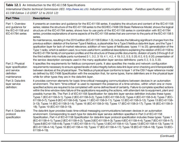
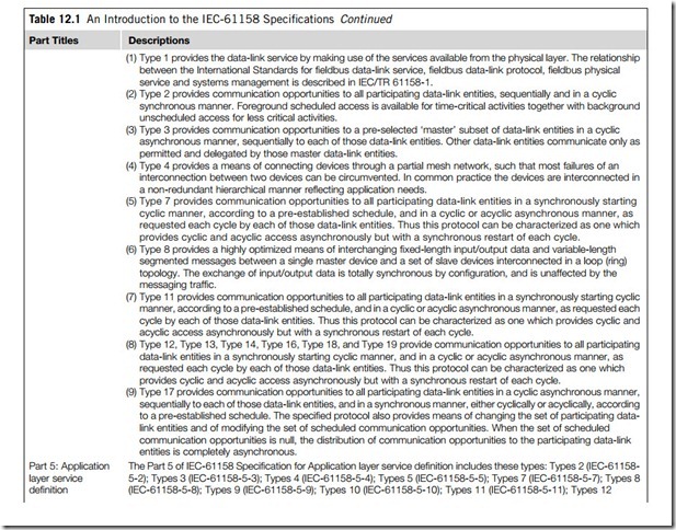
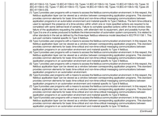
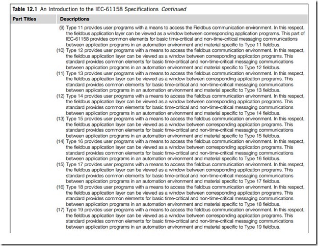
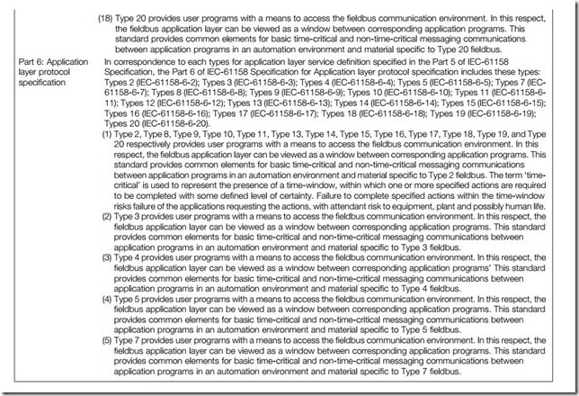
More than 100 different types of fieldbus are available, of which only a few have become established as standard. These work with a family of industrial computer network protocols for real-time distributed control, now standardized as IEC-61158. This was the final program of international fieldbus standards that was established in 2000. From Table 12.1 we learn that IEC-61158 is composed of six parts. Parts 1 and 2 are an introductory guide, a physical layer specification and service definition. Parts 3 and 4 are a data-link service definition and a data-link protocol specification, and finally, parts 5 and 6 are an application layer service definition and protocol specification.
In addition, there are eight types defined in the IEC-61158 standard. Type 1 through type 8 are Foundation Fieldbus H1, ControlNet, Profibus (Process Fieldbus), P-net, Foundation Fieldbus High- Speed Ethernet (HSE), World-FIP, and Interbus-S, respectively. This standard is going to have a significant effect on the development of the fieldbus.
The fieldbuses defined in the IEC-61158 standard are those most important for industrial applications.
(1) Foundation Fieldbus
The Foundation Fieldbus is the leading organization dedicated to a single, international, interoperable fieldbus standard. Foundation Fieldbus is a digital, serial, 2-way communications system that inter- connects field devices such as sensors and actuators, with programmable controllers. At the field level in a plant control network, it routinely serves as a local-area network (LAN) for process control. It has
a built-in capability to distribute control applications across the network, its communication models can be client/server, publisher/subscriber, and event notification, and it commonly exists in a three- layer model corresponding to the OSI reference model. The physical layer changes an electrical signal into a physical signal, the data-link layer controls messages transmitted on the fieldbus, and the application layer interfaces between the data-link layer and the flexible manufacturing system, using message transmission by standard message form.
There are two kinds of fieldbus protocol in Foundation Fieldbus: Foundation Fieldbus H1 and Foundation Fieldbus HSE (H2).
Foundation Fieldbus H1 is type 1 in IEC-61158, and is used in control applications such as the control of temperature, level, and flow. The speed of H1 is 31.25 kbps, 1 Mbps or 2.5 Mbps. It is also able to supply power for field devices directly and use the existing lines for 4 20 mA analog devices. Physical media are twisted-pair or fiber-optic. Network topology is star or bus. Data transfer size is 128 bytes. MAC (medium access control) is scheduling. Error checking is 16 bit cyclical redundancy checking (CRC). Maximum devices are 240/segment. The diagnostic method used is remote diagnostics.
Foundation Fieldbus HSE (H2) is a high-speed Ethernet protocol. The backbone network always runs at 100 Mbps. Although the H2 Fieldbus does not always use Ethernet protocol, it is generally used in the application of advanced process control, remote I/O and fast factory automation. It uses a 16 kHz alternating current signal to give support for supplying power using current mode. The signaling voltage of H2 is 5.5 to 9.0 Vp-p. Physical media are twisted-pair or fiber. Network topology is star. Data transfer size is varied and uses TCP/IP. Arbitration method is CSMA/CD. Error checking is CRC.
(2) Profibus
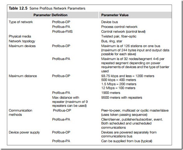
Profibus (or prifiBUS) was introduced in 1993. It utilizes a non-powered two-wire (RS-485) network which may have up to 126 nodes. It can transfer a maximum of 244 bytes data per node per cycle. Maximum communication (baud) rate is 12 Mbps with a maximum distance of 100 meters. The maximum distance is 1200 meters at 93.75 kbps without repeaters.
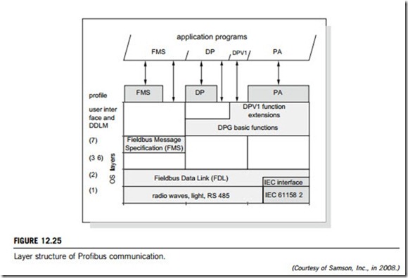
Profibus provides services at layers 1, 2 and 7 of the OSI model, although layer 2 also provides some functions of layers 3, 4 and 5. The physical layer (layer 1) can be RS-485 (2- or 4-wired cables) or fiber-optic.
Profibus-DP (Distributed Peripheral) is designed especially for communication between controllers and field devices at the field level. Profibus-DP can be used to replace parallel signal transmission with 24 V or 0 20 mA. Its transmission follows RS-485 or fiber-optic. Topology is bus. Physical media are twisted pair shielded copper cable. Transmission speed is 9.6 kbps at 1200 meters, 12 Mbps at 100 meters. Up to 127 nodes are connected with 32 devices within 1 segment.
Profibus-FMS (Flexible Manufacturing Systems) defines a large number of powerful communication services for both master/master (peer-to-peer) and master/slave communication models. The lower layer interface defines the representation of the FMS services on the data transmission protocol of layer 2. Topology is also bus.
Profibus-PA (Process Automation) permits field devices to be connected on one common bus line even in intrinsically safe areas. Profibus-PA permits data communication and power over the bus using 2-wire technology. Profibus-PA system is based on both Profibus-DP communication and IEC-61158-2 communication services. This fieldbus has the speed of 31.25 kbps.
(3) Interbus
Interbus is an open systems approach to a high-performance, ring-based, distributed device network for manufacturing and process control. The type 8 fieldbus defined in the IEC-61158 is the Interbus-S. The ring system topology actively connects devices via a closed-loop path with a transmission rate of 500 kbps. Due to the ring structure and because it has to carry the logic ground, Interbus-S requires a 5-wire cable between two devices. A distance of 400 meters between two devices is possible due to the RS-485 point-to-point transmission. The integrated repeater function in each device enables an overall extension of Interbus-S up to 13 km; maximum number of devices equals 512 nodes.
(4) World-FIP
World-FIP is the accepted fieldbus technology in a European Standard (EN-50170) which guarantees its stability and openness. World-FIP is a single communication technology for both time-critical data and unscheduled messages. A single communication technology serves each level of control archi- tecture. Physical layer characteristics include topology standardized to IEC-1158-2; 31.25 kbps, 1 Mbps, or 2.5 Mbps data rates via twisted-pair copper cable or 5 Mbps via fiber-optic cable; 64 nodes per cable segment, with up to four segments through repeaters; and 1-kilometer (km) segment length, depending on data rate, cable, and number of nodes. World-FIP uses the producer/consumer model with a centralized bus scheduler.
(5) LonWorks
LonWorks operates over greater distances and is a practical peer-to-peer network, extensible to many thousands of points, though it can be comparatively slow and more complex. Two physical-layer signaling technologies, twisted-pair “free topology” and power line carrier, are typically included in each of the standards created around the LonWorks technology. The two-wire layer operates at 78 kbps using differential Manchester encoding, while the power line achieves either 5.4 or 3.6 kbps, depending on frequency.
(6) ControlNet
ControlNet is also an open network protocol, conceived as the ultimate high-level fieldbus network and designed to meet several high-performance automation and process control criteria. Of primary importance is the ability to communicate with 100% determinism, while achieving faster responses than traditional master/slave and poll-strobe networks.
At its physical layer, the network topology can be tree, bus, or star. ControlNet can operate with single or dual coaxial cable bus for cable redundancy. Maximum cable length without repeaters is 1 km and the maximum number of nodes on the bus is 99. Repeaters can be used to further extend the cable length. Fiber-optic cables can also be used.
At the data-link layer, ControlNet is a scheduled communication network designed for cyclic data exchange. The protocol operates in cycles, known as NUT (network update time). Each NUT includes two phases; the first dedicated to scheduled traffic, where all nodes with scheduled data are guaranteed a transmission opportunity, and the second dedicated to unscheduled traffic. There is no guarantee that every node will get an opportunity to transmit in every unscheduled phase. Both phases uses implicit token ring media access control. The end of each NUT is marked by the transmission of a moderator frame by the node. The maximum size of a scheduled or unscheduled ControlNet data frame is 510 bytes.
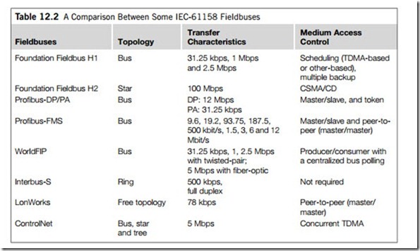
The fieldbuses defined in IEC-61158 have not only similar characteristics, but also have specific features. In Table 12.2, such fieldbuses are compared and analyzed with regard to topology, transfer characteristics and medium access control the most important aspects for performance. From this table, one can see that ControlNet is organized by topology of tree, bus, or star, so arrangement problems are thought to be under good control in ControlNet. It can also be seen that the Foundation Fieldbus HSE is very fast, at 100 Mbps, and it can be compared to the organization of the MAC (medium access controller) chipset. The Foundation Fieldbus H1 uses scheduling. The Foundation Fieldbus HSE uses CSMA/CD. Time division multiple access (TDMA) is also used for medium access control in fieldbus networks. Concurrent TDMA and synchronous TDMA are alike as they have the same speed. Interbus does not require medium access control.
(2) Fieldbus networks and protocols
The OSI reference model published by the International Standards Organization (ISO) is an established definition of network communications. It defines seven generic layers required by a communication standard capable of supporting vast networks. The first two layers in the OSI reference model, namely the physical and the data-link layers, incorporate the technologies to realize a reliable, relatively error-free, high-speed communication channel among the communicating devices. It provides support for all standard and medium-dependent functions for physical communication. The data-link layer manages the basic communication protocol as well as error control set up by higher layers.
In a fieldbus, communication takes place over fixed network routing, and transport layers are redundant. Moreover, in an industrial control environment, the network software entities or processes are also generally invariant. In such a situation, requirements of the session and the presentation layers are also minimized, so the third, fourth, fifth and sixth layers of the OSI reference model have been omitted in fieldbus protocols, meaning most fieldbus networks utilize only three OSI model layers 1, 2 and 7. Below we discuss each of these three layers of the fieldbus in more detail.
(1) The physical layer
Fieldbus allows options for three types of communication media at this layer, namely, wire, fiber-optic and radio. The physical layer is divided into an upper and a lower section. The upper section ensures that the selected media interfaces in a consistent way with the data-link layer, regardless of the media used. The lower sections define the communications mechanism and media for example, for wire medium they describe signal amplitudes, communication rate, waveform, wire types, etc.
A field network can be implemented through the compartmentalization of the bus system in segments that can be connected over repeaters. Standard-transmission rates can be in the range of about 10 kbps to 10 Mbps. The topology of the single bus segment is a line structure (bus) with short drop cables. Transmission distances up to 12 km are possible with electrical configuration, and up to 23.8 km with optical configuration, with distances being dependent on transmission rate. With the help of repeaters, a tree structure can also be constructed. The maximum number of nodes per bus segment is 32. More lines can be connected under one another through performance enhancements (repeaters); it should be noted that each repeater counts as a node. In total a maximum of 128 nodes are connectable (over all bus segments).
(2) The data-link layer
The fieldbus data-link layer protocol is a hybrid, capable of supporting both scheduled and asynchronous transfers. Its maximum packet size is 255 bytes, and it defines three types of data-link layer entities: a link master, a basic device, and a bridge. Link master devices are capable of assuming the role of the bus master, also called the link active scheduler (LAS).
As mentioned before, the LAS controls communications traffic on the fieldbus. This is also called bus master function. The active LAS grants a right to transmit to each device on a fieldbus in a pre- defined manner. Devices other than LAS can communicate only when they have the right to transmit. There are two ways of granting a right to transmit; one is by polling, which grants this right to each device in sequence. Another is by time slot method, which grants the right at a fixed time interval. The LAS combines these two methods to meet the requirements of precise cyclic (scheduled) updates and acyclic (unscheduled) traffic.
Cyclic (scheduled) communications are used for regular, periodic transmission to a field device to publish (send message) information. All other devices on the fieldbus listen to the published information and receive the message if they are designated subscribers.
Acyclic communications send special commands such as retrieval of diagnostic information or acknowledgement of alarms to the designated fieldbus devices. Once a request for data transmission is initiated, the LAS will issue a special token to each device in turn, thereby allowing them access to the bus to transmit data or request data from another device, utilizing the bus up to an allocated time limit.
(3) The application layer
The application layer converts data and requests for services from the user into demands on the communication system in the layers below, and to provide the reverse service for received messages.
Thus, it abstracts the technical details of the network from the user, who can view the network devices to which communication is needed as if they are connected by virtual point-to-point communication channels.
There are two types of data transmission: byte-oriented and bit-oriented. Both protocols function equally well in automation applications. Byte-oriented protocols can be either asynchronous or synchronous, and bit-oriented protocols organize data packets into a series of bits, in which the packets are sent without any gaps in the message. The difference between bit- and byte- oriented transmission can be seen in the hardware used for each; only bit-oriented protocols have dedicated chips for communications. Both function equally well in automation applications.
There are three models used for communication in fieldbus networks: master/slave (client/server), peer-to-peer (master/master), and publisher/subscriber (scheduling). In the first, one master polls one or more slave devices using a request/response mechanism. Usually there is a single master, although some protocols allow more than one. Profibus can be designed with a primary master and a secondary master, and has an arbitration mechanism to allow multiple masters to share the fieldbus.
A different strategy is to use peer-to-peer networking which reduces the overhead on the master, compared with centralized or single-master solutions. In this case, each slave has time to use the bus, and can exchange data with other slaves without involving the master. A bus arbitration scheme is used to determine when a device can access the bus.
Foundation Fieldbus
In 1992, an international group, the ISP (Interoperable Systems Project), was founded. In 1994, the ISP and the FIP merged to form the Fieldbus Foundation with the intention of creating a single, inter- national fieldbus standard for hazardous environments to use as the IEC-standardized fieldbus. The Fieldbus Foundation utilized some elements from the FIP and the Profibus-PA Fieldbus for the specification of their Foundation Fieldbus.
Foundation Fieldbus is an all-digital, two-way, multiple-drop communication system that brings the control algorithms into equipment and instrumentation. It has two communication protocols: H1 and HSE. The first, H1, transmits at 31.25 kbps and is used to connect the field devices. The second protocol, High Speed Ethernet (HSE), uses 10 or 100 Mbps Ethernet as the physical layer, and provides a high-speed backbone for the network.
H1 and HSE were specifically designed as complementary networks. H1 is optimized for traditional process control applications, whilst HSE, which employs low-cost Ethernet equipment, is designed for high-performance control applications and plant information integration. The combined H1/HSE Fieldbus solution allows for full integration of basic and advanced process control, and hybrid/batch/discrete control subsystems, with higher-level, supervisory applications. The combined H1/HSE Fieldbus solution provides optimized enterprise performance by removing unneeded I/O conversion equipment and controllers, sensor networks, and gateways. This flat, integrated architecture improves diagnostic methods and operator information, thus enhancing performance and reducing costs of controlled production systems.
In this system, the characteristic feature of distributed data transfer enables single field devices to execute automation tasks so that they are no longer “just” sensors or actuators, but contain additional functions. For the description of a device’s function(s), and for the definition of uniform access to the data, the Foundation Fieldbus contains predefined function blocks to be discussed later on. When
implemented in a device, they provide information about the tasks that the device can perform. Typical functions provided by some types of device are shown in Table 12.3.
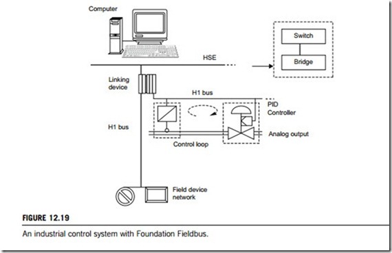
Foundation Fieldbus provides a shift of automation tasks from the control level down to the field level (Figure 3.1) resulting in the flexible, distributed processing of control tasks. Architected to a LAN network for all devices including field and control devices, Foundation Fieldbus supports digital encoding of data and many types of message. Unlike many traditional systems, which require a set of wires for each device, multiple Foundation Fieldbus devices can be connected to the same set of wires. It overcomes some of the disadvantages of proprietary networks by offering a standardized network. A simple fieldbus network setup is shown in Figure 12.19.
(1) Foundation Fieldbus H1
There are six conceptual parts to a fieldbus network: links, devices, blocks and parameters, linkages, loops, and schedules.
(1) Links
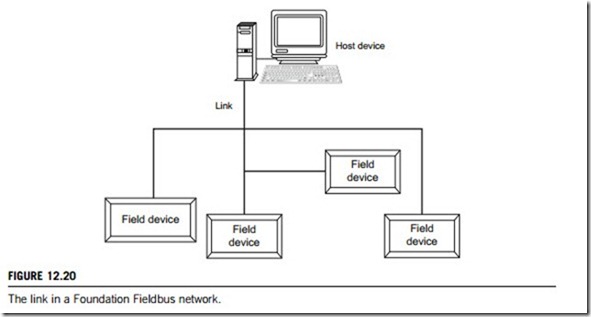
A Foundation Fieldbus network is made up of devices connected by a serial bus. This serial bus is called a link (also known as a segment). A fieldbus network consists of one or more links, each configured with a unique link identifier.
The devices on the network can be field or host devices (PCs, workstation computers, or distributed control systems), configured with a physical device tag, an address, and a device identifier. The physical device tag must be unique within each fieldbus system, and the address must be unique within each link. The manufacturer assigns a unique identifier to the device. Figure 12.20 shows a link in a Foundation Fieldbus network.
(2) Devices
A key objective for Foundation Fieldbus is interoperability, so devices from a variety of manufacturers can be linked to take advantage of both the standard and the unique capabilities of every device. Instead of requiring that device manufacturers use only a given set of functions, Foundation Fieldbus uses device descriptions, which describe all the functions in a device. Using this, the host in a control system can obtain the information needed to create an interface that configures parameters, calibrates, performs diagnostics, and accomplishes other functions on the device.
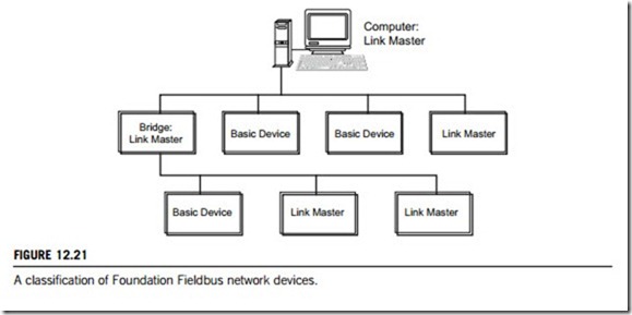
There are three types of devices on a Foundation Fieldbus H1 network: link masters, basic devices, and H1 bridges.
(i) Link master. A link master device is capable of controlling traffic on a link by scheduling the communication on the network. Every fieldbus network needs at least one link-master-capable device either an interface board in a PC, a programmable controller, a distributed control system, or any other device, such as a valve or a pressure transducer. Link masters need not be separate devices; they can have I/O functionality (for example, you could buy temperature transmitters both with and without
link master capability). Fieldbus can operate independently of a computer system because of link masters on the bus, which have processing capability and are capable of controlling the bus. After you download a configuration to your device(s), your control loop can continue to operate even if the monitoring computer is disconnected.
All of the link masters receive the same information at the time of download, but only one link master will actively control the bus at a given time. The one currently in control is called the link active scheduler (LAS). If the current LAS fails, the next link master will take over transparently and begin controlling bus communications where the previous LAS left off, so no special configuration is required to implement redundancy. The LAS device follows the schedule downloaded during the configuration process. At the appropriate times, it sends commands to other devices, telling them when to broadcast data. It also publishes time information and grants permission to devices to allow them to broadcast unscheduled (acyclic) messages, such as alarms and events, maintenance and diagnostic information, program invocation, permissives and interlocks, display and trend information, and configuration.
(ii) Basic device. A basic device is not capable of scheduling communication. They cannot become the LAS.
(iii) H1 Bridge. Bridge devices connect links together into a spanning tree. They are always link master devices and they must be the LAS. An H1 bridge is a device connected to multiple H1 links whose data-link layer performs forwarding and republishing between and among the links. Note: be aware of the difference between a bridge and a gateway. While a bridge connects networks of different speeds and/or physical layers, a gateway connects networks that use different communication protocols. Figure 12.21 shows these three types of device.
(3) Blocks
Blocks can be thought of as processing units. They can have inputs, settings to adjust behavior, and an algorithm which they run to produce outputs, and they also know how to communicate with other blocks. The three types of blocks are the resource block, the transducer block, and the function block.
(i) Resource block. A resource block specifies the general characteristics of the resource including the device type and revision, manufacturer identifier, serial number, and resource state. Each device has only one resource block, which also contains the state of all of the other blocks in the device. It must be in automatic mode for the device to execute. The resource block is a good place to start troubleshooting if the device is not behaving as desired, since it has diagnostic parameters to help determine the cause of problems.
(ii) Transducer blocks. Transducer blocks read from physical sensors into function blocks. Decoup- ling the function blocks from the hardware details of a given device, and so allowing generic indication of function block input and output.
The transducer block knows the details of I/O devices and how to read the sensor or change the actuator. It performs the digitizing, filtering, and scaling conversions needed to provide the sensor value to the function blocks, and/or makes the change in the output as dictated by the function block. Generally, there will be one transducer block per device channel, although in some devices, multiplexers allow multiple channels to be associated with one transducer block.
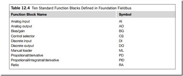
(iii) Function blocks. Function blocks provide the control and I/O behavior. Usually, a device has a set of functions it can perform represented as function blocks within the device. A function block can be thought of as a processing unit. They are used as building blocks in defining the monitoring and control application. The Foundation Fieldbus specification Function Block Application Process defines a standard set of function blocks, including 10 for basic control and 19 for advanced control. Table 12.4 shows the 10 function blocks for the most basic control and I/O functions.
Function block parameters, used for changing the behavior of a block, are classified as follows: input parameters receive data from another block; output parameters send data to another block; contained parameters do not receive or send data they are contained within the block.
(4) Linkages
The function blocks configured to control a process are linked, or connected by configuration objects inside the devices. These linkages allow data to be sent from one block to another. A linkage is different from a link, in that a link is a physical wire pair that connects devices on a fieldbus network, and a linkage is a logical connection that connects two function blocks.
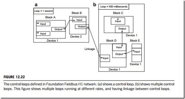
(5) Loops
A loop means a control loop which is a group of function blocks connected by linkages executing at a configured rate which sets the rate of execution, and also of data transfer. Figure 2.22 shows a control loop. It is possible to have multiple loops running at different rates on a link. Even if loops are running at different rates, they can send each other data through linkages. Figure 12.22 (a) and (b) show an example of multiple loops with linkage.
(6) Schedule
The schedule can be divided into two parts: a function block schedule that determines when a block executes, and a publishing schedule that determines when data parameters are published over the fieldbus. The function block schedule is downloaded to the particular device that contains it, and the publishing schedule is downloaded to a device or devices that have link master capability. As discussed earlier, the link master that is currently executing the publishing schedule, and thus controlling the process, is the link active scheduler.
(2) Foundation Fieldbus HSE
The Foundation Fieldbus HSE is based on standard Ethernet technology. The required components are therefore widely used and are available at low cost. When Fieldbus HSE runs at 100 Mbit/s, it cannot be equipped only with electrical lines, but needs fiber-optic cables as well.
Ethernet operates by using random (not deterministic) CSMA bus access. This method can only be applied to a limited number of automated applications because it requires real-time capability. The extremely high transmission rate enables the bus to respond sufficiently fast when the bus load is low and there are only a few devices.
If the bus load must be reduced due to the number of connected devices or if several HSE partial networks are to be combined to create a larger network, Ethernet switches must be used as shown by
the dashed square containing a switch and bridge in Figure 12.19. The switch reads the target address of the data packets that must be forwarded, and then passes the packets on to the associated partial network. This approach optimizes bus load and the resulting bus access time.
A communications network that consists of an H1 bus and an HSE network results in the topology illustrated in Figure 12.19 with the dashed square of switch and bridge. To connect the comparatively slow H1 segments to the HSE network, coupling components, so-called bridges, are required. Similar to HSE, the specification of this bus component has not yet been completed. A bridge is used to connect the individual H1 buses to the fast High-Speed Ethernet. The various data transfer rates and data telegrams must be adapted and converted, considering the direction of transmission. This way, powerful and widely branched networks can be installed in larger workshops and plants.
(3) Layered communications model
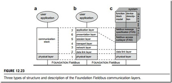
The Foundation Fieldbus specification is based on the layered communications model and consists of three major functional elements (Figure 12.23(a)): physical layer; communication stack; and user application.
The user application is made up of function blocks and the device description. It is directly based on the communication stack. Depending on which blocks are implemented in a device, users can access a variety of services. System management utilizes the services and functions of the user application and the application layer to execute its tasks (Figure 12.23(b) and (c)). It ensures the proper cooperation between the individual bus components, as well as synchronizing the measurement and control tasks of all field devices with regard to time.
The Foundation Fieldbus layered communications model is also based on the OSI reference model.
As is the case for most fieldbus systems, and in accordance with the IEC specification, layers three to six are not used. The comparison in Figure 12.23 shows that the communication stack covers the tasks of layers two and seven, and that layer seven consists of the fieldbus access sublayer (FAS) and the fieldbus message specification (FMS).
A device that sends data to other devices is called a publisher. A device that needs data from a publisher is called a subscriber. The LAS uses publisher/subscriber information to tell the publisher devices when to transmit their data over the bus. These scheduled data transfers are done in a deterministic manner, following the schedule developed in the configuration software and downloaded to the link masters.
Profibus Fieldbus
The history of Profibus (Process Fieldbus), or prifiBUS, goes back to an association venture project supported by the public authorities, which began in 1987 in Germany. Within the framework of this venture, 21 companies and institutions joined forces and created a strategic fieldbus project. Its goal was the realization and establishment of a bit-serial fieldbus, required for the standardization of the field device interface. For this purpose, the relevant member companies of the ZVEI (Central Asso- ciation for the Electrical Industry) agreed to support a mutual technical concept for plant and process automation.
The first step of this effort worked out the specification of the complex communications protocol Profibus-FMS (Fieldbus Message Specification), which was tailored to fit demanding communication tasks. A further step in 1993 saw completion of the specification for the more simply configured and faster Profibus-DP (Decentralized Periphery) which is now available in three functionally scaleable versions; Profibus-DPV0, Profibus-DPV1 and Profibus-DPV2.
The third variant, Profibus-PA (Process Automation), was developed by the Profibus User Organization as a lower-speed, intrinsically safe counterpart to Profibus-DP for supplying the required hazard resistance of process automation. This variant is based on the services provided by the Profibus- DPV1, and is implemented as a partial system embedded in a higher-level Profibus-DP communication system.
International standardization of a fieldbus system is necessary for its acceptance, its establishment and its benefits. Profibus achieved national standardization in 1991 and 1993 in DIN-19245, Parts 1-3. However, these initial standards neglected the intrinsic safety and bus supply for Profibus, which greatly restricted its applications. Only when the international standard IEC-1158-2 was published in October 1994 did Profibus become a suitable transmission technique in industrial control systems. Then in 1996, it obtained Europe-wide standardization in EN-50170. Together with other fieldbus systems, Profibus has been standardized in IEC-61158 since 1999. In the course of these activities, the latest developments of Profibus were incorporated into this standard.
Now all three Profibus variants (Profibus-FMS, Profibus-DP, Profibus-PA) operate on one stan- dardized bus access method. They are also able to use the same transmission technique (RS-485) and operate simultaneously on the same bus line. The transmission media used include either twisted-pair shielded cables for the Profibus-FMS or Profibus-DP, fiber-optics or radio waves. In the area of process automation, Profibus-PA connects process control stations and automated systems to field devices, thus replacing the analog 4 20 mA transmission technique. In addition to simple start-up and self- diagnostic functions, the fast fieldbus communication provides users with the option of realizing real-time-capable state control systems, as well as monitoring status and error messages parallel to the process. Coupled with the development of numerous application-oriented profiles and a rapidly growing number of devices, Profibus began its advance in factory automation and, since 1995, in process automation. Today, Profibus is a leading fieldbus in the world market.
(1) Profibus systems
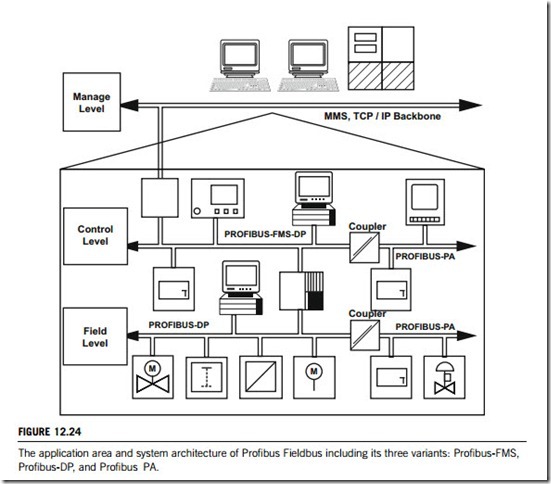
The latest Profibus family consists of three compatible versions: Profibus-FMS (Fieldbus Message Specification), Profibus-DP (Decentralized Periphery), and Profibus-PA (Process Automation).
The initial version of Profibus was Profibus-FMS, designed to communicate between programmable controllers and computers at the control level (Figure 3.1) for sending complex information between them. Unfortunately, being the initial effort of Profibus designers, the Profibus-FMS tech- nology was not as flexible as needed, and the protocol was not appropriate for less complex messages, or for communication on a wider, more complicated network. New types of Profibus-FMS have satisfied those needs so that it is still in use today, though the vast majority of users find newer solutions to be more appropriate.
The Profibus-DP was optimized for high speed and inexpensive hook-up. It has been designed and optimized particularly for communications between controllers or computers at the control level and decentralized field devices at the field level, so it communicates via cyclic data traffic exclusively. Each field device exchanges its input and output data with the control device within a given cycle time. In process engineering as well as in building process automation, operation and monitoring tasks require a visualization device in addition to the automation device. They require that device data be read or written during operation independently of the control cycle. Since the original Profibus-DP specifications did not provide any special services for these tasks, appropriate function extensions were defined in 1997. These extensions can be implemented optionally and are compatible with the existing Profibus-DP protocol and all earlier versions. The first extended Profibus-DP variant is referred to as Profibus-DPV0. In addition to the cyclic Profibus-DP communication services provided by Profibus-DPV0, Profibus-DP also offers acyclic services for alarm messages, diagnostics, parameterization and control of the field devices with other extended variants such as Profibus-DPV1 and Profibus-DPV2.
Profibus-PA is a protocol designed for process automation. In actuality, it is a type of Profibus-DP application profile which standardizes the process of transmitting measured data. Profibus-PA was designed specifically for use in hazardous environments. Unlike the automated applications in manufacturing engineering which require short cycle times of few milliseconds, other factors are of importance in process automation, such as intrinsically safe transmission techniques, field devices powered over the bus cable, reliable data transmission, and interoperability. To obtain these capa- bilities, Profibus-PA Fieldbus, along with its application profile in most environments, is able to support power over the bus.
These three variants of Profibus have been specified for different applications, as shown in Figure 12.24. Profibus-FMS is designed to communicate between programmable controllers and computers at the control level. Profibus-DP has been designed for communications between controllers or computers at the control level and decentralized field devices at the field level. Profibus-PA was designed specifically for use in hazardous environments at both control and field levels. The intrinsically safe Profibus-PA is usually part of a hierarchically structured network topology (Figure 12.24). It is connected to a Profibus-DP bus system on which also not intrinsically safe slaves and Profibus-PA bus masters operate via segment coupler.
Profibus is a smart fieldbus technology. Devices on the system connect to a central line, and once connected, these devices can communicate information in an efficient manner, and can go beyond automation messages. Profibus devices can also participate in self- and connection diagnosis. At the
most basic level, Profibus benefits from superior design of its OSI reference model layers and basic topology. Table 12.5 lists some of Profibus network parameters.
(2) Profibus transmission and communication
All variants of Profibus are based on the OSI reference model for communication networks. The layer structure of Profibus is shown in Figure 12.25. Due to field requirements, only OSI layers 1 and 2 are identical in these three variants of Profibus. The OSI layer 7 is only for the Profibus-FMS; the user interface of application programs is implemented for Profibus-DP and Profibus-PA.
(1) Physical layer
Profibus provides different versions of the physical layer as a transmission technology. All versions are based on international standards. There are two ways to realize the transmission technique for
Profibus-PA: either directly using the RS-485 standard, or in compliance with IEC-61158-2. When using the RS-485 interface, Profibus-FMS, Profibus-DP and Profibus-PA can be operated together on a common bus line. Intrinsically safe transmission in explosion-hazardous areas, however, requires the installation to be in accordance with IEC-61158-2. However, the masters of a Profibus- PA system, the control and operating stations, always operate on a Profibus-DP bus line in a safe area.
(i) Segment coupler. A bus coupler or segment coupler is installed between the Profibus-DP and the Profibus-PA segment. The coupler ensures electrical isolation between the safe and the intrinsically safe bus segment, powers of the Profibus-PA bus segment, adapts the transmission technique from RS- 485 to IEC-61158-2, and converts between asynchronous and synchronous telegrams. In Figure 12.24 there are two couplers between a Profibus-DP and a Profibus-PA segment.
(ii) Network topology. All devices are connected in a bus structure (line). The maximum permissible line length depends on the transmission rate. Up to 32 stations (masters or slaves) can
be connected in a single segment, the beginning and end of which are fitted with an active bus terminator. Both bus terminators have a permanent power supply to ensure error-free operation. The bus terminator is usually switched in the devices or in the connectors. If more than 32 stations are implemented, or there is a need to expand the network area, repeaters must be used to link the individual bus segments.
(iii) Cables and connectors. The properties of a fieldbus are also determined by the electrical specifications of the transmission cable. Although IEC 61158-2 does not specify a particular cable, the use of a reference cable is recommended (Type A, which has these parameters: twisted wire pair and shielded, 0.8 mm2 wire diameter, 1900 meters cable length including stub lines). Only this type of cable enables data transmission over distances of up to 1900 meters. For an optimum electromagnetic compatibility, the bus lines must be shielded. This shield, as well as the metal cases of the field devices, must be grounded. Different cable types are available for connecting devices either to each other or to network elements (segment couplers, links and repeaters). Profibus cables are offered by a wide range of manufacturers.
(2) Data-link layer
The efficiency of the communication system is determined by the functions and services of the data- link layer, because it specifies significant tasks, such as the bus access control, the structure of data telegrams, basic communication services, etc. These tasks are performed by the fieldbus data link and fieldbus management.
A fieldbus data link manages bus access control (medium access control), telegram structure, data security, availability of data transmission services, send data with no acknowledge and send and request data with reply. Fieldbus management provides several management functions, for example: setting of operating parameters, report of events as well as the activation of service access points.
(i) Bus access and addressing. In Profibus communication, multiple-master systems are possible.
The hybrid bus access control system operates on the token-passing method and uses the master/slave principle to communicate with the passive participants. Each master receives the token within a precisely defined time frame which allows it to have sole control over the communication network within that time frame.
(ii) Telegram structure. The Profibus-PA data telegrams of the IEC-61158-2 transmission are to a large extent identical with the Fieldbus Data Link telegrams of the asynchronous RS-485 trans- mission. Fieldbus Data Link defines the following: telegrams without data field (6 control bytes), telegrams with one data field of fixed length (8 data and 6 control bytes), telegrams with a variable data field (0 to 244 data bytes and 9 to 11 control bytes), brief acknowledgement (1 byte) and token telegram for bus access control (3 bytes).
(iii) Communication services. The data-link layer provides the application layer with send and request data with reply, and send data with no acknowledge communication services. For the former, the master issues a command or sends data to the slave and receives a reply within a defined time span. This reply either consists of an acknowledgement (brief acknowledgement) or is the requested data. In the send data with no acknowledge, the data are sent to a whole group of slaves. This permits event- controlled synchronization, where all slaves set their outputs simultaneously (synchronous mode) or update their input data simultaneously (freeze mode). A master-controlled bus assignment for slave replies is not possible in this case so that SDN telegrams remain unacknowledged. The access of the application to these basic forms of communication, as well as the various data-link services based on them is granted via so-called service access points which are used by the higher layers (user interfaces in some of Profibus networks) to perform all communication tasks of the respective application program.
(3) Profibus device management
The field devices in Profibus systems, as in other types of fieldbus systems, provide a wide range of information and also execute functions previously performed by programmable controllers and control systems. To do this, tools for commissioning, maintenance, engineering and parameterization of these devices require an exact and complete description of device data and functions, such as the type of application function, configuration parameters, range of values, units of measurement, default values, limit values, identification, etc. The same applies to the controller or control system, whose device- specific parameters and data formats must also be made known (integrated) to ensure error-free data exchange with the field devices.
The illustrations in Figure 12.25 show that the OSI layer 7 (application layer) is only used with Profibus-FMS; the OSI layers 3 to 6 are not used with these three Profibus variants. Figure 12.25 also shows that both Profibus-DP and Profibus-PA systems utilize a uniform user interface and also can be considered as standardized applications of the data-link layer (the OSI layer 2).
Therefore, the field device management of Profibus systems is a function layer that is defined as a “user interface” in many of related technical documents. It has several elements or descriptions, including the following.
(1) Device database files
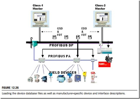
Profibus has developed a number of methods and tools for this type of field device description which enable standardization of device management. The performance range of these tools is optimized to specific tasks, which has given rise to the term scaleable device integration. Therefore the tools are put together in one specification for Profibus with three volumes, which are: generic station description (GSD), field device tool (FDT), and electronic device descriptions (EDD). These methods and tools are routinely used in master stations, such as controllers and computers, at the control level for both Profibus-DP and Profibus-PA.
The interface description based on FDT, and the device description EDD, both aim at enabling the class-2 master to represent and operate the full scope of functions of all field devices. The most flexible way to operate is to load and update them when still in the project planning phase (see Figure 12.26).
(i) Generic station description (GSD). A GSD defines a device database file, provided by the device manufacturer and containing a description of the field devices either in Profibus-DP or in the Profibus- PA system. These files allow an open configuration tool to obtain device manufacturer and device identification number, transmission rate and bus parameters, number and format of the data for cyclic communication (for instance, cyclic positioner data), reference variable, controlled variable, final position feedback and status messages (fail-safe position, control loop fault, on-site operation, etc.). There are two ways to use these files. The first applies to compact devices whose block configuration is
already known, and the second is for modular devices whose block configuration is not yet conclusively specified on delivery. In the latter case, the user must use the configuration tool to configure them in accordance with the actual module configuration.
(ii) Field device tool (FDT). The existing description languages for configuration and parameterization of field devices require an “auxiliary tool” that allows device manufacturers to provide users with expanded and specific characteristics of their field devices in standardized form over standardized interfaces. The definition of an auxiliary tool provides a universal interface with the ability to implement suitable software components on all automation systems fitted with it. Such an interface has been specified and designated a field device tool.
(iii) Electronic device descriptions (EDD). The GSD is inadequate for describing application-related parameters and functions of a field device (for example configuration parameters, ranges of values, units of measurement, default values, etc.). However, process automation required a more powerful description language, which has been developed in the form of the universally applicable EDD language. This language provides the tools to describe the functionality of field devices, and also contains support mechanisms to integrate existing profile descriptions in the device description, allow references to existing objects so that only supplements require description, allow access to standard dictionaries, and allow assignment of the device description to a device. Using this language tool, device manufacturers can create the relevant file for their devices which, like the GSD file, supplies device information to the engineering tool and then subsequently to the control system.
(2) Device profiles
Profibus achieves standardization of all device functions and parameters as well as the access to these data by using so-called device profiles, which determine how to implement communication objects, variables and parameters for the different types of field devices.
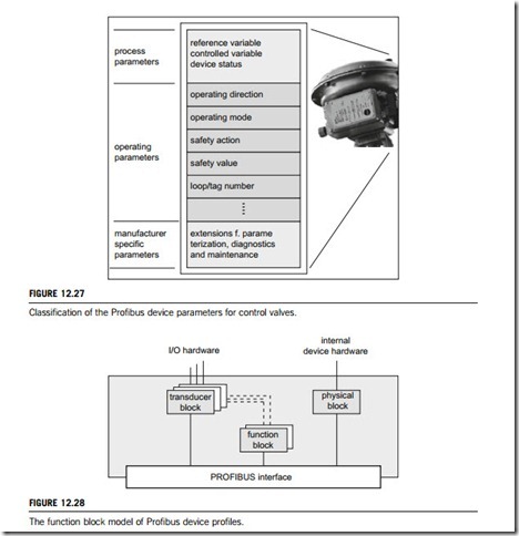
(i) Classification of device parameters. The field device parameters and data which can be accessed through communication can be divided into three groups: process parameters, operating parameters, and manufacturer-specific parameters. As an example, these three groups of parameters for a control valve are partially given in Figure 12.27.
(ii) Function block model. With device profiles, Profibus operates on the basis of a function block model. This model groups the different device parameters into several functional blocks which ensure uniform and systematic access to all parameters. Due to its object-oriented assignment of device parameters and device functions, the function block model simplifies planning and operation of distributed automation systems. Additionally, this model ensures compatibility with the international fieldbus standard so that a conversion to an international fieldbus protocol would not require modification of the application software.
The function block model assigns dynamic process values and the operating and standard parameters of a field device to different blocks (Figure 12.28). The function block describes the device function during operation (cyclic data exchange of analog input/output, alarm limit values, etc.). The physical block encompasses all parameters and functions required to identify the hard- ware and software (revision numbers, limit values, etc.). The transducer block contains the parameters which describe coupling signals to the process and are required to pre-process the data in the field device (process temperature and pressure, characteristic curves, sensor type, etc.). The operating mode, including start-up, operation, maintenance or diagnosis, determines which
parameters and blocks must be used. For instance, during operation, function block parameters are used almost exclusively, while during maintenance and start-up, transducer and physical block parameters are used. For diagnosis, information is required from all three blocks. During operation, a transducer block can be assigned to each function block. The process and system data saved in the transducer blocks can be used by the field device to pre-process its own data and, thus, to provide the master with extended process information. The more extensive the transducer blocks defined by the device profile, the more varied is the process information provided by the respective field device.
