Direct Current Generator
Another method of supplying excitation current is with the use of a self-excited direct current generator mounted on the rotor shaft. The amount of excitation current is adjusted by controlling the field current of the generator. The output of the armature supplies the excitation current for the rotor. Since the generator is self-excited, it does not require an external source of direct current. Although that is an advantage over sup- plying the excitation current through slip rings or with a brushless exciter, the generator does contain a commutator and brushes. The generator generally requires more maintenance than the other methods.
Automatic Starting for Synchronous Motors
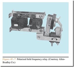
Synchronous motors can be automatically started as well as manually started. One of the advantages of a synchronous motor is that it provides good starting torque with a relatively low starting current. Many large motors are capable of being started directly across the line because of this feature. If the power company will not permit across the line starting, synchronous motors can also employ autotransformer starting, reactor starting, or wye-delta starting. Regardless of the method employed to connect the stator winding to the power line, the main part of automatic control for a synchronous motor lies in connecting excitation current to the rotor at the proper time. The method employed is determined by the manner in which excitation is applied to the rotor. In the case of manual excitation, the field discharge switch is used. Brushless exciter circuits often employ electronic devices for sensing the rotor speed in order to connect DC excitation to the rotor at the proper time. If a direct current generator is employed to provide excitation current, a special field contactor, out-of-step relay, and polarized field frequency relay are generally used.
The Field Contactor
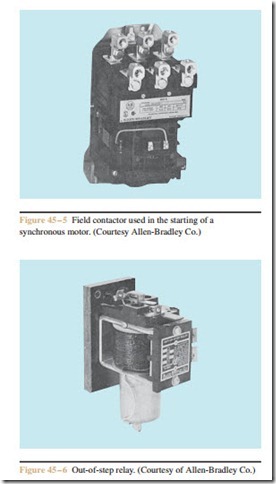
The field contactor looks very similar to a common three- pole contactor (Figure 45 – 5). This is not a standard contactor, however. The field contactor contains a DC coil and is energized by the excitation current of the rotor. The field contactor serves the same function as the field discharge switch discussed previously. The two outside contacts connect and disconnect the excitation current to the rotor circuit. The middle contact connects and dis- connects the field discharge resistor at the proper time.
Out-of-Step Relay
The out-of-step relay is actually a timer that contains a current-operated coil instead of a voltage-operated coil. The coil is connected in series with the field discharge resistor. The timer can be pneumatic, dashpot, or elec-
tronic. A dashpot type of out-of-step relay is shown in Figure 45 – 6. The function of the out-of-step relay is to disconnect the motor from the power line in the event that the rotor is not excited within a certain length of time. Large synchronous motors can be damaged by excessive starting current if the rotor is not excited within a short time.

