Electrical degrees are used as a reference in electrical machines. Electric motors and alternators both have their poles arranged in a circle. The poles are placed symmetrically and precisely in the circle. Each pole equals 180 electrical degrees.
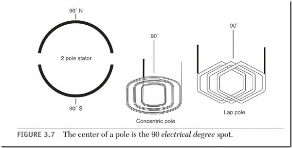
Electrical degrees are used to describe a location on a pole. The center of a pole is 90 0 from the edge of the first coil of a pole (Fig. 3.7). This reference
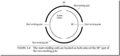
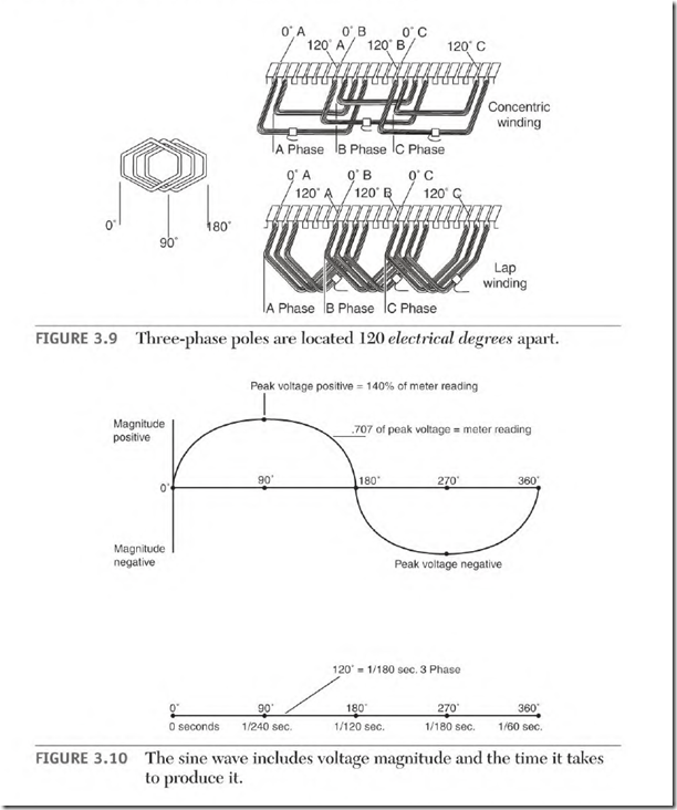
point is where a single-phase motor’s start-winding pole is placed in relation to the run-winding pole (Fig. 3.8). Three-phase machines separate the phases 120 0 apart (Fig. 3.9).
One cycle of alternating current is produced by passing a magnet over two (180 0 ) poles of a phase. One cycle is equal to 360 electrical degrees.
The time taken to produce one cycle is also expressed in degrees (Fig. 3.10). Electrical degrees are used to specify the exact time (in relation to the voltage) that something occurs during a cycle. For example, if amperes and voltage are out of step (explained under “Inductive Reactance, ” later in the
chapter), electrical degrees are used to describe the length of time that they are separated.
The word angle is used to describe the amount of separation (in time). An example is phase angle (phase means winding and angle means time).
Electrical Degrees and Mechanical Degrees
Two stator poles produce one cycle of power. Each pole contains 180 electrical degrees. A two-pole stator has the same number of electrical degrees as mechanical degrees. In a four-pole stator, there are 720 electrical degrees in the 360 mechanical degrees of the stator (Fig. 3.11).
Degrees and Location
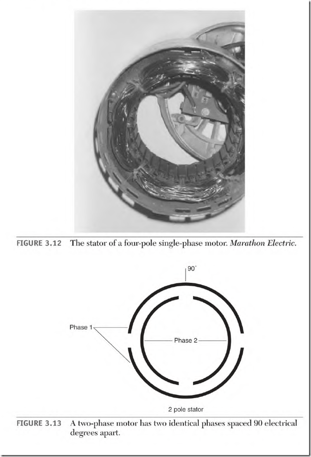
Degrees are also used to reference a location on a pole. An example of this is the position of the start and run windings of a single-phase stator (Fig. 3.12).
The 90 0 spot of a run-winding pole is the center of the pole (Fig. 3.7). The start-winding coils are located on either side of this spot (Fig. 3.8). Three single-phase windings of a three-phase motor are located 120 electrical degrees apart (Fig. 3.9).
Two-Phase Power
A two-phase alternator is shown in Fig. 3.13. There are two identical singlephase windings located 90 electrical degrees apart. When a DC field is rotated in this stator, two out-of-step voltages are produced. The two voltages are separated by 90 electrical degrees in time (1/240 second at 60 Hz).
Two-Phase Rotating Magnetic Field
When 60-Hz two-phase voltage is applied to the windings of a two-phase motor, the peak magnetic strength of its two windings will occur 1/240 second apart. This creates a rotating magnetic field in the stator.
The motor’s rotor will try to rotate at the same speed as the two-phase alternator’s DC field. Varying the speed of the alternator will vary the speed of the motor.
The rotating magnetic field of an AC motor is created when the current flows in each phase at a different time. When the time (in electrical degrees) that current flows in each phase matches the location (in electrical degrees) of the poles in each phase, the rotating magnetic field is at its effective best.
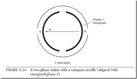
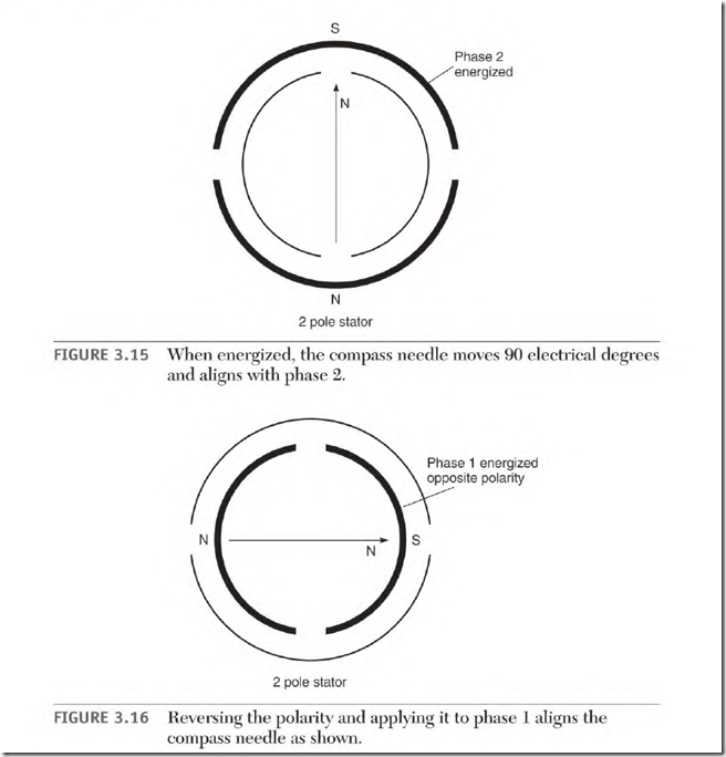
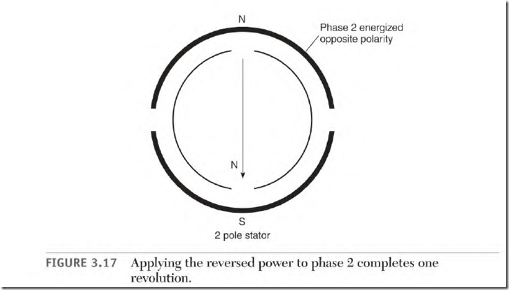
Figure 3.14 shows a two-pole, two-phase stator with a compass in its bore. Energizing phase 1 with low-voltage DC will cause the compass to align as shown in Fig. 3.14. Energizing phase 2 with the same polarity moves the compass needle 90 0 as shown in Fig. 3.15. Reverse the DC polarity and apply it to phase 1. The compass moves another 90 0 as shown in Fig. 3.16. Apply the reversed polarity to phase 2 and the compass needle aligns as shown in Fig. 3.17. Reverse the DC polarity and apply it to phase 1, and the needle will have made a complete revolution. This is a simplified version of the rotating magnetic field that occurs when two-phase voltage is applied to a two-phase winding.
The synchronous RPM of most AC motors is determined by the number of poles and the Hz of the power source. The following formulas give the synchronous speed of AC induction and synchronous motors:
Hz x 60 seconds (to get cycles per minute) x two poles = numerator
Numerator + poles = RPM
Numerator + RPM = poles
60-Hz numerator = 7200
A two-pole motor on 60 Hz:
7200 + 2 poles = 3600 RPM
Thro-pole synchronous speed (at any Hz) divided by the motor’s pairs of poles = synchronous speed of the motor:
For 60 Hz: 3600 + pairs of poles = RPM
For 50 Hz: 3000 + pairs of poles = RPM
The Single-Phase Alternator
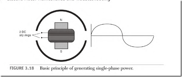
Single-phase power is generated when a DC magnet is rotated past a singlephase winding (Fig. 3.18). As the magnet starts across a single-phase pole, the voltage generated builds to its peak value when the magnet and the pole are aligned. The voltage value drops to zero as the magnet goes past center and exits the pole. As the magnet enters the next pole, the voltage generated is of the opposite polarity. The voltage value will increase to a peak value and then decrease to zero.
Current, Ampere, Power, and Reactive Terms
Many combinations of terms are used with current amperes and power. Current, amps, and amperes are used interchangeably. Current is used to describe the fact that amperes of some type (lagging, leading, in unity with voltage) are flowing in a circuit. Ampere flow (or amps flowing) also signifies current in a circuit.
The current exchange between a coil and the power source may be called magnetizing current, magnetizing amperes, reactive current, reactive amperes, and reactive amps. The current between a capacitor and the power source may be referred to as reactive current, leading current, leading amperes, leading amps, reactive amperes, and reactive amps.
The amperes required to do work, or which are part of a wattmeter’s result, are called true amps, true amperes, real amps, and real amperes.
Power terms include apparent power, real power, power factor, lagging or leading power factor, and actual power. All power includes both amperes and volts.
The term reactive can apply to both leading (capacitive) and lagging (inductive) descriptions.
The following text describes the effect different components have on the amperes of a circuit and the condition of a circuit’s power.
Related posts:
Incoming search terms:
- electric current degrees
- which formula is used to calculate the total elecrical degree in stator of an a c motor?
- total electrical degree formula for stator of ac motor
- 120 electrical degrees apart
- the total electrical degree of 4 pole machine winding is
- total electrical degree of 4 pole ac machine
- what is electrical degrees
- What is the reason to occur 120 electrica degree between poles
- Which formula is used to calculate the totalelectrical degree in stator of an A C motor?
- the electric degree of 6 pole of AC motor is
- pole stator winding ground fault
- Phase apart winding formula
- motor ke electrical degree dhundhne ka sutra
- how many electrical degree make one cycle
- formula to calculate total electrical degree in stator of an A C motor
- electrical degree of 6 pole
- ac motar satar electric degree
- 2 phase windings is electrical degrees
- which formula used to calculate the total electrical degree on stator of an ac motor
