Objectives
After studying this unit, the student will be able to:
• Describe field current protection for a de motor
• Describe the use of series resistance for limiting the armature current when starting a de motor
• Connect a timed starting control for a de motor
When large de motors are to be started, cur rent inrush to the armature must be limited. One method of limiting this current is to connect resis tors in series with the armature. When the arma ture begins to turn, counter-emf is developed in the armature. As counter-emf increases, resistance can be shunted out of the armature circuit, per mitting the armature to turn at a higher speed. When armature speed increases, counter-emf also increases. Resistance can be shunted out of the circuit in steps until the armature is connected di rectly to the power line.
Limiting the starting current of the armature is not the only factor that should be considered in a de control circuit. Most de motor control circuits use a field current relay (FCR) connected in series with the shunt field of the motor. The field cur rent relay insures that current is flowing through the shunt field before voltage can be connected to the armature.
If the motor is running and the shunt field opens, the motor will become a series motor and begin to increase rapidly in speed. If this happens, both the motor and the equipment it is operating can be destroyed. For this reason, the shunt field relay must disconnect the armature from the line if shunt field current stops flowing.
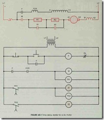
The circuit shown in figure 45-1 is a de motor control with two steps of resistance connected in series with the armature. When the motor is started, both resistors limit current flow to the ar mature. Time-delay relays are used to shunt the starting resistors out of the circuit in time intervals of five seconds each until the armature is con nected directly to the line.
The circuit operates as follows: When the start button is pushed, current is supplied to relay coil F and all F contacts change position. One F contact is connected parallel to the start button and acts as a holding contact. Another F contact connects the field current relay and the shunt field to the line.
When shunt field current begins to flow, con tact FCR closes. When contact FCR closes, a cir cuit is completed to motor starter coil M and coil TRI. When starter M energizes, contact M closes and connects the armature circuit to the de line. Five seconds after coil TRI energizes, contact TRI closes. This permits current to flow to relay coils Sl and TR2. When contact Sl closes, resistor Rl is shunted out of the circuit. Five seconds after relay coil TR2 energizes, contact TR2 closes. When contact TR2 closes, current can flow to coil S2. When contact S2 closes, resistor R2 is shunted out of the circuit and the armature is connected directly to the de power line.
When the stop button is pushed, relay F de energizes and opens all F contacts. This breaks the circuit to starter coil M which causes contact M to open and disconnect the armature from the line. When coil TRl de-energizes, contact TRl opens immediately and de-energizes coils S1 and TR2 . When coil TR2 de-energizes, contact TR2 opens immediately and de-energizes coil S2. All contacts in the circuit are back in their original positions, and the circuit is ready to be started again.
REVIEW QUESTIONS
1. Why is resistance sometimes connected in series with large de motors?
2. Is the field current relay a current relay or a voltage relay?
3. What happens if the motor is operating and the shunt field current stops flowing?
4. Describe the action of this circuit if TRl and TR2 are replaced with off-delay relays.
