Subsonic Protection and High-Pass Filtering
Rationale
All loudspeakers have a low-end limit; their bass response does not go endlessly deeper.
Subsonic (infrasonic) information, comprising both music content and ambient information, may occur below the high-pass “turnover” frequency (or low-end roll off) of the bass loudspeaker(s). It will not be reproduced efficiently.
Note: While potentially within humans’ aural perceptive range, subsonic signals are “below hearing” (strictly infrasonic) in the sense of being “out-of-band” to, and only faintly or at least reducingly reproducible by, the sound system.
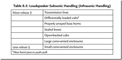
Loudspeakers vary in their ability to handle large subsonic signals. Small ones may or may not be heard but won’t ever cause damage. Large subsonic signals are more
risky with some kinds of loading. An approximate ranking of subsonic signal handling robustness is shown in Table 8.5. Individual designs can vary widely, however.
Subsonic Stresses
Other than straining the speaker(s), if the amplitude of the subsonic (really infrasonic) signal(s) is large enough, then significant amplifier capability will be wasted. At the very least, the unrealizable portion will cause unnecessary amplifier heating and electricity consumption.
If the amplifier is also being driven hard, the presence of a large subsonic signal will reduce the threshold for clipping and also thermal shutdown. The amplifier will behave as if rated at only a fraction of its actual power capability. There are broadly two approaches to the problem.
The Pro Approach
Subsonic filtering may be regarded as an essential part of editing and sweetening in recording. “Subsonic” frequencies (“sub” here being rather loosely designated as any “out of context/too-low bass information”) are usually removed before amplification by HP filters (HPF) with fixed, switchable, or sweepable roll-off frequencies, usually available on each channel or group of a mixing console. Alternatively, HP filtering may even be available “up front” as a switch on some microphones or on portable, location tape machines.
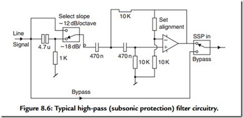
Generally, such filters are at least –12 dB/octave and, more usefully, the steeper –18-dB/ octave (Figure 8.6) or even –24-dB/octave. They may be occasionally appended to professional power amplifiers, as well as to preceding active crossovers, on the basis of providing “maximum” (read: brute force) protection at all costs, in this guise they are described as “subsonic protection” (SSP). Often this facility is superfluous and repeated needlessly, as the mixer and active crossover already do or can provide subsonic filtering.
Logistics
The mixer can provide SSP most flexibly per channel, solely for those sources requiring filtration. The active crossover may provide overall back-up subsonic protection, in case a mic without HPF’ing on its channel is dropped.
When subsonic protection is fitted to and relied upon in amplifiers alone, there will be an enforced and unnecessary repetition and diversification of resources in any more than the simplest, two-channel PA. If subsonic filter provision is made in an amplifier, it should be
switchable (or programmable or otherwise controllable) so that its action can be removed positively when not required.
Indication
A few power amplifiers have light-emitting diodes (LEDs) (often jointly error indicators) that indicate subsonic activity or protection shutdown arising from excess subsonic levels. This kind of protection is most common where the maker is also a speaker maker or where the amplifier is closely associated with a particular speaker, as the protection’s frequency–amplitude envelope that will allow the most low frequency action is very specific to the cabinet and driver used.
Overall, in high performance professional power amplifier designs benefiting from modem knowledge, filtration and any HP filtering are avoided as far as possible or else minimized by adaptive circuitry.9
Hi-End Approach
In “hi-end” hi-fi and professional power amplifiers, high-pass filtering is (or should be) depreciated or at least kept to the bare minimum, for two reasons.
First, all practical HP filters progressively delay low frequencies relative to the rest of the music. Every added HP filter pole only adds to this “signal smearing.”10 Simulation in time and frequency domains shows this.11
Second, HP filters require the use of capacitors. Capacitors that are almost ideal for audio and not outrageously expensive and bulky are limited in type and values. Capacitors that are faradically large enough not to cause substantial “signal smearing” are, in practice, medium-type electrolytics, and not in practice nor in theory anywhere near so optimal for audio as other dielectric types.
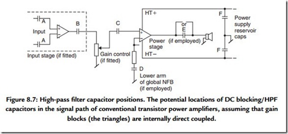
For these reasons, even routine HP filtering (alias DC blocking or ac coupling) may be absent altogether. Figure 8.7 shows the points where HP filtering occurs in the majority of otherwise direct- and near-direct-coupled power amplifiers.
Low Approach
In “consumer-grade” audio power amplifiers, HP capacitors are made as small as possible in value while maintaining what is judged by casual listening or first-order theory to
be an acceptable point for the bass response low cutoff frequency (f3L). The result is considerable HP filtering, permanently engaged. Subsonic signals may then rarely pose a problem, but sonic quality may be degraded up into midfrequencies, while a great deal of the music’s ambient cues is lost.
Direct Coupling
When all HP filtering is removed, a power amplifier becomes direct—or ‘DC’ (direct current)—coupled. ‘DCC’ would have been better, but that now means something else. Extending the response to zero frequency, that is, “down to DC,” is achieved readily at the design stage with most transistor topologies. The advantages are sonic, and substantial, due to the excision of intrinsically imperfect parts and the removal of an intrinsically unnatural filtration, and the signal-delay and the possible charge accumulation on asymmetric music signals it brings. For this is the truth of all signal path HPF capacitors, both those in series and in NFB arms. Whether DC coupling is safe or workable in a particular amplifier is a separate design question.
With conventional valve amp topologies, the response to DC is not fully achievable, except in the few workable ‘OTL’ designs. However, it is still possible to direct couple the remainder of a valve amplifier, with global DC NFB taken before the transformer. In fact, the first precision DC amplifiers were valve op-amps.
Direct Current Management
With direct-coupled circuitry, unwanted DC “offset voltages” will be amplified by the power amplifier’s respective stage gains. Excess DC is of great concern and must be avoided. It can be (i) produced internally, by mismatches in resistor or semiconductor values or by intrinsic topological asymmetry or (ii) introduced externally, from preceding DC-coupled signal sources.
Internally produced DC offsets may be kept to safe levels by precision in design and component selection. This requires matching of two or three apposite parameters of the differential pair at the front end of each stage, assuming some version of the conventional high NFB “op-amp” type of architecture. The “pair” might be BJTs, FETs, or valves. And to ensure that the source resistances (at DC) seen by each input leg are the same,
or close, and not too high either, depending on bias current. If the resistor values then conflict with CMR, the latter should have priority, in view of EMC requirements, and the nonrecoverability of the CMR opportunity. Direct current balance may be restored by other means, for example, current injection.
Externally applied DC, appearing on the inputs, because of essentially healthy but imperfect preceding equipment, will usually be in the range of 0.1 to 100 mV. More than
+/–100 mV would suggest a DC fault in the preceding source equipment. Assuming a gain of 30X , this would result in 3 V at the amplifier’s output. Because such a steady offset will eat up headroom on one-half of the signal swing, the clip level is lowered asymmetrically. A direct coupled power amplifier should not be harmed by this and should also protect the speakers it is driving, but equally it is entitled to shut down to draw attention to such an unsatisfactory situation. In the most advanced designs of analogue path yet published,9 DC coupling is adaptive: if DC above a problem level persists at the input, DC blocking capacitors are automatically installed and the user is informed by LED.
Some low-budget domestic power amplifiers have long offered part and manual direct coupling. The power stage may not be wholly direct coupled, but at least the DC blocking capacitor(s) at the input can be bypassed via a second “direct” or “laboratory” input.
The user is expected to try this but revert to the ordinary ac-coupled inputs if DC on the source signal is enough to cause zits and plops. A blocking capacitor(s) at the input can be bypassed via a second “direct” or “laboratory” input.
Autonulling
Direct current offset may be continually forced to near zero volts by a servo, which is another name for brute-force VLF and DC feedback, applied around an amplifier overall, or just the input or output stage. Servos have been de rigueur in U.S. and U.S.-influenced high-end domestic power amplifiers for some years. Alas, those who have designed
them into high-performance power amplifiers have clearly not thought through the consequences. Tellingly, servos are not usually nor likely to be found in amplifiers with truly accurate sounding bass.
The reasons are clear enough today: servos cause the same or even wilder distortions in LF frequency and/or phase response, and/or signal delay vs. frequency (group delay). Figure 8.8 shows this.
They also compromise the integrity of the circuitry they are wrapped around by increasing noise susceptibility, while the capacitor imperfections that DC coupling is supposed to overcome are reintroduced, as distortion-free DC servo action depends on an expensive, bulky, high-performance capacitor for integration. In this way, the DC servo returns us to before square one, with the added cost and complexity. Worse, the original thinking behind servo’ing was to save money (!) on input transistor and part matching, as a servo will “fix” any DC in its range, often up to +/–5 V, including DC appearing on the equipment input. This is neat, but like so many “smart” options, DC servo’ing is not quite suitable for audio.


