The Brushless Exciter
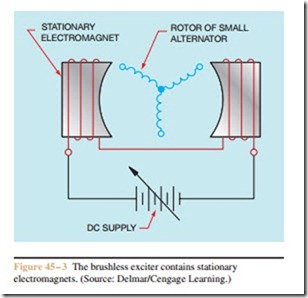
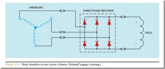
A second method of supplying excitation current to the rotor is with a brushless exciter. The brushless exciter has an advantage in that there are no brushes or slip rings to wear. The brushless exciter is basically a small three-phase alternator winding and three-phase rectifier located on the shaft of the rotor. Refer to the photo- graph in Figure 45 – 1. At the back of the rotor a small winding can be seen. This is the winding of the brush- less exciter. Electromagnets are placed on either side of the winding (Figure 45 – 3). A three-phase rectifier and fuses are also located on the rotor shaft. The rectifier converts the three-phase alternating current produced
in the alternator winding into direct current before it is supplied to the rotor winding (Figure 45 – 4). The amount of excitation current supplied to the rotor winding is controlled by the amount of direct current sup- plied to the electromagnets. The output voltage of the alternator winding is controlled by the flux density of the pole pieces.

