PERFORMANCE TIPS
Obtaining added performance by modifying the fuel and exhaust systems usually involves other changes to the engine as well. Simply changing fuel or exhaust system components without simul taneously making other engine alterations severely restricts the performance increase available. Thus, it is common that in installing multiple carbu retors the engine will also be equipped with cylin der heads with a higher compression ratio as well as a special camshaft. It is the combination of the three that provides a performance increase out of proportion to the individual contribution of mul tiple carburetion, a racing cam or boosted com pression.
The art of engine modification to increase out put is so advanced that literally tens, if not a hundred, of different combinations are available for every production engine. It would be impos sible to list all such combinations here so basics will be discussed instead.
Before going into details, several precautions should be mentioned. If an engine is to be modi fied it must be in excellent mechanical condition and be of a good design. Most American produc tion engines are of such design and can be safely modified provided they are sound mechanically. Bad rings, sloppy pistons, burned valves, etc., not only detract greatly from any performance gains that might be achieved they also physically en danger the safe running of the engine. The other warning is made to conserve your own time and energy. It is far easier, faster and safer to install high performance equipment obtained from the car manufacturers themselves or from a specialty producer of speed equipment than it is to try and build it yourself.
Basic Concepts
A look at a typical “heat balance ” chart, Fig.226, shows what an inefficient machine an internal combustion engine is. The heat balance simply shows what percentage of the energy available from the burning of the fuel is turned into useful work, how much is lost as heat to the exhaust and cooling systems, what quantity is lost to friction in turning the engine over, etc. If any of these losses can be reduced, engine performance will be in creased by a corresponding amount. It is as simple as that.
Reducing the losses, however, is not a simple matter. All production engines represent compro mises in design in order to make them reliable, quiet, tractible, and reasonably economical under a wide variety of driving conditions. When modi fying such an engine, a small sacrifice in reliabil ity, for example, will be tolerated by the builder in return for a performance increase. Similarly, a somewhat louder car is not objectionable to the driver in return for the livelier performance avail able with straight-through muffiers. One is, in effect, almost invariably trading off-compromis ing-some element of engine operation in order to get the increased performance.
Provided one is willing to sacrifice something for it, reducing heat losses becomes another matter. How actually is it done? Engineers speak of the three basic elements of internal combustion engine performance as: 1. Thermal efficiency; 2. Mechanical efficiency and; 3. Volumetric effi ciency. Increasing any one of them improves per formance and is accompanied by a corresponding rise in useful work output on the heat balance (there are exceptions to this rule and they will be remarked as they come up).
Thermal efficiency is concerned with the actual burning of the fuel and is traditionally improved by a variety of techniques including changing valve timing and lift, increasing the compression ratio and other innovations. Few changes in the fuel and exhaust systems will affect thermal effi ciency so we are not concerned with it except as noted later. Mechanical efficiency is an expression of the amount of friction developed in the engine as a result of simply running it as a machine. It is generally quite high and can safely be ignored as a significant approach to higher outputs.
Volumetric efficiency is the direct result of how an engine “breathes” and can be much enhanced by fuel and exhaust system modification. Other factors enter into the question of engine breathing such as valve size, lift and timing, but many aspects of fuel and exhaust system design affect it profoundly. Supercharging, multiple carburetors, fuel injection, intake and exhaust “tuning”, mani fold and port design, are but several conventional routes to increased performance via increasing engine volumetric efficiency.
Ports
Intake and exhaust port size and shape are very important in letting an engine breathe properly. While much has been written on the subject, there is still much confusion between theory and practice.
In the forefront of any discussion is the ques tion of port shape. Many people labor under the illusion that round ports are superior to rectangu lar ones. This is decidedly not the case and since many modern VS engines have square or rec tangular ports, long, weary hours with a rotary file will be saved if this fact is remembered. Actually, it is not whether a flat sided port is better or worse than a circular one but, rather, which of them is better in a given situation? Even this point is the subject of much research effort by the car com panies and a definitive answer is not available.
The safest course, then, is to leave the ports the same shape they were originally. Apart from any other consideration, there is always the point that there may not be enough metal in the port area of the cylinder head casting to permit changing their shape.
This must also be taken into account before attempting to enlarge the ports substantially. Ideally, port area on both intake and exhaust should be equal to the area between, respectively, intake and exhaust valves and their seats when the valves are fully open. This presumes a separate port for each valve. Modern engine design is good in this respect and only when high lift camshafts are used are the ports usually enlarged.
The most important usc of port alteration is in the matter of matching the manifold ports with the cylinder head ports. They should mate as close to perfectly as possible. Checking such alignment requires an extremely accurate template or one of the machinists’ techniques such as the use of prus sian blue on one of the surfaces. Intake and exhaust manifold gaskets are generally not suit able to use as templates because they are deliber ately made somewhat oversize to take care of some mismatching in port size and location.
A final point and the most hotly debated of all, How much good docs polishing the ports do? The theory is that polishing provides better gas flow. In fact, flow velocity is very much slower at the sides of the port than it is even a little way in toward the center so it doesn’t make that much difference if the port walls are a trifle rough. What is very important, though, is to remove any large projections in the ports-thicker, say, than 0.010 in.-such as casting marks because they do ob struct gas flow.
Carburetors
It is almost as bad for performance to have too many carburetors as too few. Improving volu metric efficien cy by providing more carburetor throat are-either by adding carburetors or using ones with larger throats-is a good idea but can easily be overdone.
Two opposing factors must be considered when engine carburetion is changed. First, it is desirable to provide as much carburetor throat area as possible to reduce restriction in the intake system and improve engine breathing. But, at the same time throat area must not be so large that poor atomization of the fuel results which cuts down on the engine’s thermal efficiency. It is the question of air velocity through the carburetors that is critical.
The larger the carburetor throat area, the lower will be the air velocity. Air requirements change with engine speed so at low RPM, when much less air is needed, velocity is less to begin with. Veloc ity is about 10 times higher at maximum RPM than jt is at low engine speeds. Therefore, it is obvious that a compromise must be made to assure good velocity at low speed while simul taneously providing enough throat area to prevent strangling the engine at high speed.
One method of obtaining these conflicting goals is to use carburetors with primary and secondary barrels. The primaries open at all RPM’s, but the secondaries only do so during periods of peak air demands.
A truly staggering variety of special, multiple carburetion systems are available from the car and specialty manufacturers. When buying one making your own for a VS is almost unthinkable because of the design and construction complex ities involved-the above principles should be kept in mind.
Fuel Injection
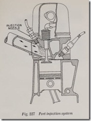
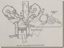
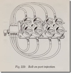
Injecting fuel directly into the cylinder in diesel engine fashion or injecting it into the port over comes the compromise necessary with carbureted engines, described in the previous section. A sepa rate injection pump and suitable nozzles or in jectors assure good atomization of the fuel regard-less of the air velocity through the intake system. An engine with fuel injection, therefore, can use “wide open” intake pipes that offer no restriction to air flow into the engine. Result, higher (close to maximum) volumetric efficiency.
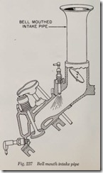
Of the two systems, the direct cylinder injection method, Fig. 228, is preferred, though generally more expensive, than port injection, Fig. 227. This is because it dispenses with even the slight restric tion of port fuel nozzles and because better atomi zation of the fuel is obtained under all engine speeds. Injection of fuel directly into the combus tion chamber has other advantages as well. Both systems1 while appearing simple, are quite com plex and require very accurate pumps and meter ing devices. On a well designed cylinder injection engine, output can go 20% higher than that avail able with carburetors.
Supercharging
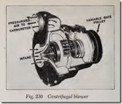
Supercharging can easily raise volumetric effi ciency over 100%. It is not difficult to see how. If an engine cylinder at a certain speed-volumetric efficiency decreases with increasing RPM on an unaspirated ( unsupercharged) engine-is only % filled by the air fuel-charge, the engine h as a volumetric efficiency of 75% at that speed. Bein g an air pump, the supercharger can produce pres sures above those resulting from the weight of the atmosphere and can completely fill the cylinder regardless of engine speed. In f act, as long as supercharger pressure exceeds atmospheric pres sure-14.7 lb. at sea level-the cylinder will re ceive more charge than an engine relying on normal breathing possibly could and volum etric efficiency goes over 100%.
The amount of over-pressure a supercharger produces is called the “boost” and an engine in top mechanical condition will handily sust ain a 5 to 6 lb. boost with very little sacrifice in engine life. With this amount of boost such an engine should put out 30% to 40% more power without other modifications. Engines have been built th at will accommodate boost pressures of up to around
50 lb. and in return have had horsepower in creased to 3 and 4 times that which a correspond ing engine without a supercharger would produce .
For high boost pressures, the engine must be modified extensively. Because supercharging is such a relatively easy route to high performance there is a tendency to overdo it. Supercharging does put greater stresses on bearings and recipro cating parts that increase rapidly with boost pres sure and the sad end of many a “blown” engine has been a blown engine.
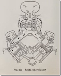
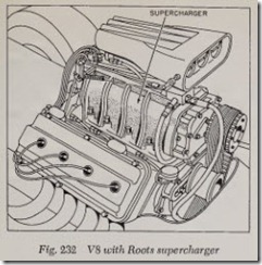
There arc two general types of blowers and three methods of driving them. Centrifugal, Fig. 230, and radial superchargers are, in effect, fans; not being, therefore, positive displacement pumps, air can slip past the moving vanes at lower speeds. Positive displacement superchargers include both charger is also, of course, a matter of boost pres sure; the higher the boost, the higher the power requirements.
An alternate method is to drive the blower by an outside pow er source such as a separate small engine or an electric motor. Such installations are obviously unsuited for ordinary street application and find use in all-out, short time competitive events.
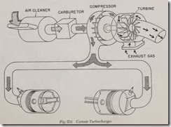
Most intriguing drive system of all is the turbo blower. Adopted from diesel engine work, the exhaust-driven blower requires no mechanical drive from the engine and is run by the engine’s own expanding exhaust gases. With a turbine wheel, like a gas turbine engine, the blower does not consume engine power during operation. Re ferring back to the heat balance, it utilizes some of the heat normally lost to the atmosphere through the exhaust. In this sense it provides a “free” supercharge.
A centrifugal blower is always linked to the turbine wheel of a turbo-blower because the ex haust gases do not provide enough energy to drive a positive displacement pump at low RPM. Con sequently, positiv e boost pressures are only avail able at higher engine RPM’s.
Exhaust System
There is a major misconception about high per formance exhaust system design. It is that great performance gains can be realized simply by re lieving the back pressure caused by conventional muffi ers, resonators and connecting plumbing. This is not true. Relieving back pressure com pletely by substituting carefully made headers terminating in wide open pipes without muffiers will only increase maximum output by 5% to 7%.
This presumes that a “tuned” exhaust system is not used. Such a system, see next section, will produce appreciably higher gains.
If, however, you decide to go for the smaller gain alone, the rules are simple. The easiest method of all is to simply install “straight through” muffiers, described earlier in the chapter, in place of the conventional muffiers and reso nators. If a VS is being modified, there should be separate exhaust systems for each bank of cylin ders . . . i.e., a dual exhaust system.
The next step is to replace the cast iron, stock exhaust manifolds with headers-specially fabri cated manifolds with longer, more gently curved pipes leading to the individual cylinders. A VS normally uses a single header for each bank of four cylinders and these are usually adequate. In general, the fewer the number of cylinders dis charging into a common exhaust system the better. Hence, 6 cylinder engines often have two separate systems of 3 cylinders each or even three systems of two cylinders each. When multiple manifolds are used, it is best to design them so that two successive cylinders in the firing order do not discharge into the same system. On a VS or a Corvair 6 this is automatically taken care of by having individual headers for each bank since on either engine the firing order jumps from one bank to the other alternately.
The important things to remember in buying or building an exhaust system are: 1. Be sure header ports match the cylinder head ports in size and location (see section, Ports); 2. There are no abrupt changes of tubing diameter leading from one part of the system to the other and; 3. All bends in the system should be gradual, not abrupt.
Intake and Exhaust System Tuning
Intake and exhaust tuning exploit a strange phenomenon that is still imperfectly understood. In so doing, they can provide performance gains that are appreciable, rivaling those of a super charger supplying a modest boost. But, in provid ing this gain, intake and exhaust tuning operate in the realm of conventional thermodynamic proc esses. Horsepower increases are strictly attribut able to reducing energy losses out the exhaust and by increasing volumetric efficiency (see Heat Bal ance, Fig. 226), not by some kind of “black magic”.
One is apt to think of a moving column of gas,be it the air-fuel mixture in the intake or the burnt gases in the exhaust, as a simple flow situation like water moving in a garden hose. There is more to it than that and gas flow is one of the most compli cated studies one can get involved in. Fortunately, we are concerned here with only one other ele ment of gas movement beside its simple flow-the wave motion.
When the exhaust valve opens at the end of the power stroke the pressure in the cylinder is very much greater than it is in the exhaust pipe. Releas ing that pressure into the exhaust pipe creates a wave motion that is superimposed on the actual flow of gas leaving the cylinder. Similarly, when the piston starts down on the intake stroke, cylin der pressure is below that of the intake system. This, in turn, creates a wave pattern in the moving intake gas; because the pressure differential is less on the intake side, the energy of its waves are less than those in the exhaust.
In both intake and exhaust, the waves gener ated are a variety of sound wave. That is, waves are created that move through the flowing gas by alternately compressing and expanding successive layers of gas like a fast acting accordion. Called sound waves of finite amplitude, they are unlike ordinary sound waves in that they carry a great deal more energy. In comparison to gas flow they travel at high velocities: while the exhaust gas at high RPM in a racing engine may be traveling at speeds to 500 MPH, its wave will be moving at rates around 1900 MPH through it. Similarly, the intake wave will be traveling at speeds of about 750 MPH through the air-fuel mixture which will be moving at about 150 MPH.
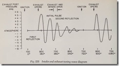
It should be obvious that the exhaust wave moving outward from the cylinder has an average pressure higher than the exhaust gas itself, and, hence, is a compression wave. When it reaches the end of an exhaust pipe-without mufflers or abrupt changes in diameter-it is reflected by the atmosphere back up the pipe as a rarefaction, or suction, wave. Fig. 235, shows this in diagrammatic form-notice that the wave continues to be re flected, first by the atmosphere then by the cylinder.
The intake wave, on the other hand, starts as a pulse of rarefaction and is reflected by the atmo sphere as a pulse of compression.
At high engine speeds (wave amplitude energy-increases with engine speed) a reflected wave in the intake, pulse of compression, can be at 2 pounds above atmospheric pressure. On the exhaust side, the reflected wave, a pulse of rare faction, may be at 6 to 8 pounds below atmos pheric.
How can these waves be utilized to increase engine performance? This is quite easy to under stand, although there are a great many elements that enter into the calculations in actual practice. If the pulse of compression in the intake arrives at the cylinder while the intake valve is still open on the intake stroke, it will force extra fuel-air mix ture into the combustion chamber and act as a “free” supercharge. That is, no engine power is lost in providing this boost and it is, therefore, free in the same sense that the boost from a turbo blower supercharger is free.
If the pulse of rarefaction reflected in the ex haust can be made to arrive at the cylinder at the end of the exhaust stroke when both intake and exhaust valves are open during the overlap period, two benefits result. First, the pulse of suction helps remove the last traces of burnt gas from the cylinder. Next, it will induce a suction in the intake system via the slightly open intake valve and help draw extra fuel-air mixture into the cylinder, again providing a free supercharge.
Many factors modify the strength of the waves as well as their affect. Tending to give better results because the pulses are stronger are: Fast opening valves (steep cam profile); early opening exhaust valves (combustion pressure is still high); high compression ratios (higher combustion pres sures); unrestricted ports; high RPM; intake and exhaust pipes of substantially constant diameter (sharp diameter changes reflect the pulses); proper intake and exhaust pipe diameter and length; and as few cylinders as possible using common manifolds (waves from other cylinders in the manifold cause disturbances that change and often negate the original wave pattern). Because the waves in the exhaust system carry more energy than do those in the intake, higher perfor mance gains are had by tuning the exhaust. It is, of course, better to tune both systems than one alone.
It can be seen that arranging things so that the correct pulses in the intake and exhaust systems arrive at the cylinder at the right moments to act beneficially is a question of timing. Timing is accomplished by making the two systems the right lengths so as to assure correct pulse arrival at a certain RPM.
The above statement exposes the major draw back of intake and exhaust tuning. Tuned systems only work at certain engine RPM’s. At other engine speeds they either do not work or work detrimentally. Detrimental affects are reduced by tuning the system for high RPM’s so that negative results are confined to low speeds where pulse strength is much lower.
It is readily apparent why tuning only produces
gains over a certain band of engine RPM’s. Wave speed remains fairly constant while engine speed varies greatly. Thus, a tuned exhaust system of a calculated length will assure correct pulse arrival at one engine speed but if the engine is running slower the pulse will arrive too early to be of bene fit. While various methods have been suggested to
eliminate this drawback-adjustable length sys tems, varying pulse speed by changing the density of the gas, etc.-none have proved too successful.
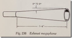
Use of a megaphone (diverging nozzle), Fig. 236, at the end of the exhaust system increases pulse amplitude and widens the band of engine speeds at which a tuned exhaust system produces performance gains. Use of bell-mouth intake pipes, Fig. 237, accomplishes the same result on the intake side. With both installed, tuning can be made to provide performance increases over a 1000 to 1500 band of engine RPM’s.
How are the length calculations made? On an engine having a separate exhaust pipe and intake pipe for each cylinder, of constant diameter, the following formula will assure the correctly timed arrival of a beneficial wave at the desired engine RPM.
L = Length of intake or exhaust system in inches from the valve to the pipe end (if a mega phone is used the measurement is made to the beginning of the mega phone).
N = Engine speed in revolutions per minute at which performance increase is desired. The specific RPM chosen should lie in the middle of the RPM band over which tuning benefits will apply.
V =Average velocity of the wave in feet per sec ond. For the intake this is the speed of sound in air-1088 Ft. per second at sea level. For the exhaust this varies from about 1300 to 1800 Ft. per second-depending on engine speed, throttle opening and load on engine, being at a maximum at high RPM, with a load and wide open throttle.
T = Time expressed in degrees of crankshaft rotation it takes for a wave to travel down the pipe, to be reflected at the open end and re turn to the cylinder. This is the point in the cycle that it is desired to have the wave ar rive. On the exhaust, T is usually chosen as the number of degrees between the opening of the exhaust valve and the middle of the overlap period when intake and exhaust valves are open together. On the intake, T is usually chosen as the number of degrees between the beginning of the intake stroke and a point just before the intake valve closes , around 180 degrees.
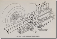
It is obvious that tuning will work on systems having more than a single cylinder firing into the tuned exhaust pipe, as witness the “bundle of snakes” exhaust systems used on Grands Prix and other V8 race car engines. These engines have four cylinders in each tuned system and the calcula tions differ from those given above. Tuned intake systems always have one intake pipe for each cylinder, as for example on a fuel injection engine where such a provision is readily available. A word of caution, so called “tuned systems” avail able from some speed equipment manufacturers are, in fact, not tuned systems at all. Measuring and judging commercially available systems by the information given in this section should help guide you in determining whether the system really is a tuned one or not.
Fuels
Changing the fuel the engine burns, of course, does not directly affect, and is little effected by, volumetric efficiency. Many different fuels have been experimented with and a few-either in the pure state or mixed with other fuels-have very great performance potential.
Basically, there are only a few relationships that must be understood to appreciate the potential of different fuels. At the outset, the calorific con tent-amount of heat released in burning-is of primary importance. A fuel of high calorific con tent will provide more power from a given engine than will a fuel with a lower value . . . if other things are equal.
They never are equal, so other things have to be taken into consideration. One is, How much air must be combined with the fuel for burning? If the calorific content of the fuel is low, such as it is with alcohol, but less air is required to burn it, a given engine may do better with such a fuel. Fig. 233 gives the calorific content of several possible fuels together with the weight of air required to combust them. The significant comparative figures up to this point are shown in the column, Heat Release per Lb. of air.
It can be seen that both ethyl and methyl alcohol compare favorably with gasoline on this basis although both have much lower calorific values. The only major difference between them being that much more alcohol would be required than gasoline and this is, of course, a minor con sideration if all-out performance is of primary importance. Because much more alcohol is needed, carburetors set up for it as a fuel would have to have larger jets.
Several other factors have to be taken into consideration in selecting a fuel for maximum performance. One is, How high a compression ratio can be tolerated with a certain fuel? In gen eral, the higher the octane rating of the fuel, shown in the first column in Fig. 233, the higher will be the permissible compression ratio. This is a factor that makes alcohol so attractive for racing higher ratios can be used with it than with most gasolines.
A final element in fuel selection is what makes the “nitros” the fuels of choice in some situations. If the fuel carries its own oxygen with it-within its own molecular structure-the engine builder
‘ can get higher outputs per pound of fuel burned. This is exactly what nitromethane and nitroben zene do.
This explanation is necessarily over simplified and before anyone begins to experiment with fuels other than gasoline he must inform himself thor oughly on the subject. Forgetting the time and expense which might be lost by setting the engine up incorrectly, there is the matter of personal safety. In addition to other dangers, several of the fuels listed are both highly volatile and extremely poisonous.
Review Questions
1. Name the components of the fuel system. . . . . . . . . . . . . . . . . . . . . . . . . . . . . . . . . .
2. How is fuel fed to the carburetor on all moden engines? . . . . . . . . . . . . . . . . . . . . . . . . . . . .
3. What is the purpose of baffie plates in a fuel tank? . . . . . . . . . . . . . . . . . . . . . . . . . . . . . . . . . .
4. Where is the fuel filter most commonly located? . . . . . . . . . . . . . . . . . . . . . . . . . . . . . . . . . . . .
5. How does water accumulate in a fuel tank? . . . . . . . . . . . . . . . . . . . . . . . . . . . . . . . . . . . . . . . .
6. What part of the engine drives a mechanical fuel pump? . . . . . . . . . . . . . . . . . . . . . . . . . . . .
7. Name the part of a fuel pump which causes fuel to flow in the fuel lines. . . . . . . . . . . . . .
8. On what part of the fuel pump does fuel pressure depend? . . . . . . . . . . . . . . . . . . . . . . . . . .
9. What type of fuel pump assists in operating the windshield wipers? . . . . . . . . . . . . . . . . . .
10. What two conditions must a mechanical fuel pump maintain in order to satisfy the fuel requirements of an engine under all operating conditions? . . . . . . . . . . . . . . . . . . . . . . . . . . . .
11. Besides filtering air, what two important functions does an air cleaner fulfill? . . . . . . . . . . . .
12. Where is a flexible fuel line usually located? . . . . . . . . . . . . . . . . . . . . . . . . . . . . . . . . . . . . . .
13. What is a carburetor? . . . . . . . . . . . . . . . . . . . . . . . . . . . . . . . . . . . . . . . . . . . . . . . . . . . . . . . . . . . .
14. What is an intake manifold? . . . . . . . . . . . . . . . . . . . . . . . . . . . . . . . . . . . . . . . . . . . . . . . . . . . .
15. Explain how the manifold heat control operates. . . . . . . . . . . . . . . . . . . . . . . . . . . . . . . . . . . .
16. If an engine were run with the exhaust pipe disconnected, the exhaust would be very noisy. Why is this so? . . . . . . . . . . . . . . . . . . . . . . . . . . . . . . . . . . . . . . . . . .
17. How does a muffier quiet the noise of exhaust? . . . . . . . . . . . . . . . . . . . . . . . . . . . . . . . . . . . .
18. What is one undesirable feature of any exhaust system? . . . . . . . . . . . . . . . . . . . . . . . . . . . . . .
19. What is the main advantage of having dual exhausts on a V8 engine? . . . . . . . . . . . . . . . . . .
20. Engine fuel is composed principally of what two elements? . . . . . . . . . . . . . . . . . . . . . . . . . .
21. What are the main advantages of gasoline as an engine fuel? . . . . . . . . . . . . . . . . . . . . . . . . . .
22. The burning of a fuel in the presence of oxygen is a process referred to by what name? . .
23. What element in the air-fuel mixture is not affected chemically by combustion? . . . . . . . . . .
24. Octane rating refers to the ability of gasoline to resist what objectionable process? . . . . . .
25. What is the ideal air-fuel ratio for an automobile engine? . . . . . . . . . . . . . . . . . . . . . . . . . . . .
26. What three conditions do the intake manifold and carburetor create that result in good vaporization of the fuel? . . . . . . . . . . . . . . . . . . . . . . . . . . . . . . . . . . . . . . . . . . .
27. In order for a carburetor to deliver fuel to an engine under all operating conditions, it must have what seven features? . . . . . . . . . . . . . . . . . . . . . . . . . . . . . . .
28. What does the throttle valve control? . . . . . . . . . . . . . . . . . . . . . . . . . . . . . . . . . . . . . . . . . . . .
29. Explain why it is necessary to have an accelerating system for satisfactory engine operation.
30. Explain how venturi action feeds gas from the carburetor bowl into the intake manifold.
31. What kind of spring operates any type of automatic choke? . . . . . . . . . . . . . . . . . . . . . . . . .
32. What type of carburetor design overcomes the effect of air resistance in an air cleaner? . .
33. What is the function of an air bleed in a carburetor? . . . . . . . . . . . . . . . . . . . . . . . . . . . . . . . .
34. How does altitude affect carburetion with respect to jet size? . . . . . . . . . . . . . . . . . . . . . . . .
35. For what reason does a four barrel carburetor give better engine performance than a two barrel carburetor? . . . . . . . . . . . . . . . . . . . . . . . . . . . . . .
36. What is an anti-percolator device on a carburetor? . . . . . . . . . . . . . . . . . . . . . . . . . . . . . . . . . .
37. What is the main difference between the primary and secondary side of a Carter WCFB Carburetor? . . . . . . . . . . . . . . . . . . . . . . . . . . . . . . . . . . . .
38. Name three types of air cleaners. . . . . . . . . . . . . . . . . . . . . . . . . . . . . . . . . . . .
39. Explain how a paper element type air cleaner may be cleaned. . . . . . . . . . . . . . . . . . . . . . . . .
40. What two basic types of automatic chokes are currently being used? . . . . . . . . . . . . . . . . . . . .
41. In the process of adjusting the carburetor idle, usually two separate adjustments have to be made. What are they? . . . . . . . . . . . . . . . . . . . . . . . . . .
42. When adjusting the idle on cars with automatic drive, which adjustment requires special attention? . . . . . . . . . . . . . . . . . . . . . . . . . . . . . . . . . . . . .
43. While loosening or tightening a fuel fitting, why is it necessary to use two wrenches? . . . .
44. What type of fuel line has to be handled with special care while bending? . . . . . . . . . . . . . .
45. What might be the two results of a clogged tank vent? . . . . . . . . . . . . . . . . . . . . . . . . . . . . . .
46. What points should be checked when an engine won’t start due to a possible defect in the fuel system? …………………………………
47. Describe a simple test for a restriction in the exhaust system. . . . . . . . . . . . . . . . . . . . . . . . . .
48. Before deciding that a car is giving poor mileage due to a mechanical condition, what important factor should be considered? . . . . . . . . . . . . . . . . . . . . . . . . . . .
49. What two tests are needed to determine whether or not a fuel pump is serviceable? . . . . . .
50. What equipment is needed to perform a fuel pump test? . . . . . . . . . . . . . . . . . . . . . . . . . . . . . .

