REDUCED-VOLTAGE STARTING METHODS
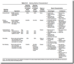
Reduced voltage starters operate such that input current and consequently torque are reduced during starting. Table 12 2 briefly describes the various methods of starting and gives features and limitations of each
When motors are started at reduced voltage, the current at the motor terminals is reduced in direct proportion to the voltage reduction, while the torque is reduced as the square of the voltage reduction. For example, if the “typical” motor were started at 65% of line voltage, the starting current would be 42% and the torque would be 42% of full voltage values. Thus reduced voltage starting provides an effective means of reducing both current and torque (Fig. 12 19)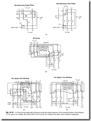
PRIMARY RESISTOR STARTING
In primary resistor starting, a resistor is connected in each motor line (in one line only in single phase starters) to produce a voltage drop due to the motor starting current. A timing relay shorts out the resistors after the motor has accelerated. Thus the motor is started at reduced voltage but operates at line voltage
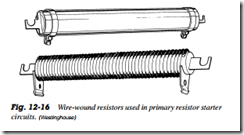
Figure 12 16 shows two types of motor starter resistors. The resistance element will retain its mechanical and electrical properties both during and after repeated heating and cooling. All metal parts are either plated with or fabricated of corrosion resistant material for overall corrosion protection. Under certain conditions operating temperatures may reach 600C and no change the resistance value. The motor starter resistors are 11, 14, 17, and 20 in long and come in wattage ratings of 450 to 1320. Table 12 3 shows the resistance ranges and other factors. Note the current handling ability of the resistors
Primary resistor starters are sometimes known as cushion starters. The main reason for the name is their ability to produce a smooth, cushioned acceleration with closed transition. However, this method is not as efficient as other methods of reduced voltage starting, but it is ideally suited for applications such as conveyors, textile machines, or other delicate machinery where reduction of starting torque is of prime consideration
Operation
Figure 12 17 is the reduced voltage magnetic starter that uses resistors to operate a three phase motor properly at start. Closing the start button or other pilot device energizes the start contactor (S) shown in Fig. 12 18. This connects the motor in series with the starting resistors for a reduced voltage start. The contactor (S) is now sealed in through its interlock (Sa). Timing relay (TR) is energized, and after a preset time interval its contacts TRTC close. This energizes the run contactor, run, which seals through its interlock run a . The contacts (run) close, bypassing the starting resistors, and the motor will now be running at full voltage. The contactor (S) and timing relay (TR) are de energized when the interlock runb opens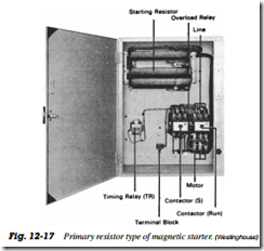
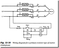
An overload, which opens the stop button or other pilot device, de energizes the (run) contactor. This removes the motor from the line
Primary resistor starters provide extremely smooth starting due to the increasing voltage across the motor terminals as the motor accelerates. Since motor current decreases with increasing speed, the voltage drop across the resistor decreases as the motor accelerates and the motor terminal voltage increases. Thus if a resistor is shorted out as the motor reaches maximum speed, there is little or no increase in current or torque
