The quasistatic (first order) or slip model of IMs with neglected stator and rotor transients may be obtained from the general model (13.70) with
dΨs = dΨr = 0 in synchronous coordinates. dt dt
(1+ ω τj 1 s ‘)Ψ = τs s ‘Vs + Kr Ψr
(1+ j(ω −ω1 r ))Ψ =r Ks Ψs
Te = − 32 p Re j1 ( Ψr ri * ); ir = σ−1 ΨLrr −Ψs L LLs m r (13.124)
pJ1 ddtωr = Te −Tload
It has been noted that this overly simplified speed model becomes erroneous for large induction machines.
Near rated conditions, the structural dynamics of low and large power induction machines differ. The dominant behavior of low power IMs is a first order speed model while the large power IMs is characterized by a first order voltage model. [20, 21]
Starting again with the third order model of (13.70), we may write the rotor flux space phasor as
This way we may separate the real and imaginary part of rotor equation of (13.70) as
Kτr ‘ ddtΨr Kr = ddtx’xδΨ= ω −ω −rKrr + x1−x’x’xVcos ; K−x’x’ Kδr τ ΨVsinr ‘ r ≈rKδKr s = LLms = LLmr r
H’dωr = −V Ψr K sinr δ− tload (13.125’) dt x’
where V (voltage), Ψr – rotor flux amplitude, x – no-load reactance, x’ – shortcircuit (transient) reactance in relative units (p.u.) and τr’, ω1, ωr in absolute units and H’ in seconds2. The stator resistance is neglected.
In relative units, ΨrKr may be replaced by the concept of the voltage behind the transient reactance x’, E’.
τr ‘ dE’ = x E’+ x − x’ Vcosδ
Kr dt x’ x’
ddtδ = ω −ω −r 1 x −x’x’ Kr Vsinτr ‘E’δ (13.126)
H’ddtωr = −V E’x’ sinδ− tload
• The concept of E’ is derived from the similar synchronous motor concept
• The angle δ is the rotor flux vector angle with respect to the synchronous reference system
• The steady-state torque is obtained from (13.126) with d/dt = 0
E’= x − x’ Vcosδ (13.127) x
ω −ω =r 1 x −x’x’ Kr Vsinτr ‘E’δ < 0 for motoring (13.128)
te = −V E’x’ sinδ = − x’1 − x1 V22 sin2δ > 0 for motoring (13.129)
for positive torque δ<0 and for peak torque δK = π/4 as in a fictitious reluctance synchronous motor with xd = x (no-load reactance) and xq = x’ (transient reactance).
For low power IMs, E’ and δ are the fast variables and ωr – ω1, the slow variable.
Consequently, we may replace δ and E’ from the steady-state Equations (13.127) and (13.128) in the motion equation (13.126). x’H’ d(ω −ωrdt 1) = −V2 x −xx’ 1+(ω −ωT’r(ω −ωr 1)T’1)2 − x’tload; T’= Kτrr‘ (13.130)
Also, from (13.127) and (13.128),
![]() E’= x 1+(xT’−2 (x’ Vω −ω)r 1)2 ; δ ≈ tan-1T'(ω −ωr 1) (13.131)
E’= x 1+(xT’−2 (x’ Vω −ω)r 1)2 ; δ ≈ tan-1T'(ω −ωr 1) (13.131)
In contrast, for large power induction machines, the slow variable is E’ and the fast variables are δ and ωr – ω1. With dωr/dt = 0 and dδ/dt = 0 in (13.126),
|
δ = sin−1 x’tload ; (ω −ωr 1)= 0 VE’ It is evident that ωr = ω1 ≠ 0. A nontrivial first order approximation of ωr – ω1 is [21] |
(13.132) |
|
ω −ω ≈ x’tload |
(13.133) |
r 1 T’ (VE’)2 −(x’tload )2
Substituting δ of (13.132) in (13.126) yields
![clip_image001[4] clip_image001[4]](http://machineryequipmentonline.com/electric-equipment/wp-content/uploads/2017/04/clip_image0014_thumb9.gif) T’ dE’ = − x E’+ x − x’ V 1− x’tload 2 (13.134)
T’ dE’ = − x E’+ x − x’ V 1− x’tload 2 (13.134)
dt x’ x’ VE’
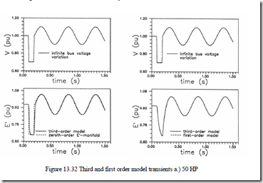
Equations (13.132) through (13.134) represent the modified first order model for large power induction machines. Good results with these first order models are reported in [20] for 50 HP and 500 HP, respectively, in comparison with the third order model (Figure 13.32).
Still better results for large IMs are claimed in [21] with a heuristic first order voltage model based on sensitivity studies.
MULTIMACHINE TRANSIENTS
A good part of industrial loads is represented by induction motors. The power range of induction motors in industry spans from a few kW to more than 10 MW per unit. A local (industrial) transformer feeds a group of induction motors through pertinent switchgears which may undergo randomly load perturbations, direct turn on starting or turn off. Alternatively, bus transfer schemes are providing energy-critical duty loads to thermal nuclear power plants, etc.
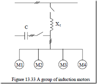
During the time interval between turn off from one power grid until the turn on to the emergency power grid, the group of induction motors, with a series reactance common feeder or with a parallel capacitor bank (used for power factor correction), exhibits a residual voltage, which slowly dies down until reconnection takes place (Figure 13.33). During this period, the residual rotor currents in the various IMs of the group are producing stator emfs and, depending on their relative phasing and amplitude (the speed or inertia), some of them will act as generators and some as motors until their mechanical and magnetic energies dry out.
![]() The obvious choice to deal with multimachine transients is to use the complete space phasor model with flux linkages Ψs and Ψr and ωr as variables ((13.54 through 13.56) and (13.64)).
The obvious choice to deal with multimachine transients is to use the complete space phasor model with flux linkages Ψs and Ψr and ωr as variables ((13.54 through 13.56) and (13.64)).
Adding up to the 5th order model of all n IMs (5n equations), the equations related to the terminal capacitor (and the initial conditions before the transient is initiated) seems the natural way to solve any multimachine transient. A unique synchronous reference system may be chosen to speed up the solution.
![]() Furthermore, to set the initial conditions, say, when the group is turned off, we may write that total stator current ist (0+ =) 0. With a capacitor at the terminal, the total current is zero.
Furthermore, to set the initial conditions, say, when the group is turned off, we may write that total stator current ist (0+ =) 0. With a capacitor at the terminal, the total current is zero.
![]()
![]()
![]() ∑j 1=n isj(0+ +) ic = 0; dVdt s = iCc (13.135)
∑j 1=n isj(0+ +) ic = 0; dVdt s = iCc (13.135)
![]()
![]() ∑ ∑n isj n − Ψsj − ΨrjLmj (13.136) j 1= = j 1= σj 1 Lsj L Lsj rj
∑ ∑n isj n − Ψsj − ΨrjLmj (13.136) j 1= = j 1= σj 1 Lsj L Lsj rj
Differentiating Equations (13.135) with (13.136) with respect to time will produce an equation containing a relationship between the stator and rotor flux time derivatives. This way, the flux conservation law is met.
![]() We take the expressions of these derivatives from the space phasor model of each machine and find the only unknown, (V s ) t= +0 , as the values of all variables Ψsj , Ψrj , ωrj, before the transient is initiated, are known.
We take the expressions of these derivatives from the space phasor model of each machine and find the only unknown, (V s ) t= +0 , as the values of all variables Ψsj , Ψrj , ωrj, before the transient is initiated, are known.
![]() Now, if we neglect the stator transients and make use of the third order model, we may use the stator equations of any machine in the group to calculate the residual voltage V ts ( ) as long as (13.135) with (13.136) is fulfilled.
Now, if we neglect the stator transients and make use of the third order model, we may use the stator equations of any machine in the group to calculate the residual voltage V ts ( ) as long as (13.135) with (13.136) is fulfilled.
This way no iteration is required and only solving each third model of each motor is, in fact, done. [22, 23] Unfortunately, although the third order model forecasts the residual voltage Vs(t) almost as well as the full (5th order) model, the test results show a sudden drop in this voltage in time. This sharply contrasts with the theoretical results.
A possible explanation for this is the influence of magnetic saturation which maintains the “selfexcitation” process of some of the machines with larger inertia for some time, after which a fast deexcitation of them by the others, which act as motors, occurs.
Apparently magnetic saturation has to be accounted for to get any meaningful results related to residual voltage transient with or without terminal capacitors.
Simpler first order models have been introduced earlier in this chapter. They have been used to study load variation transients once the flux in the machine is close to its rated value. [24, 25]
Furthermore, multimachine transients (such as limited time bus fault, etc.) with unbalanced power grid voltages have also been treated, based on the dq (space phasor) model–complete or reduced. However, in all these cases, no strong experimental validation has been brought up so far.
So we feel that model reduction, or even saturation and skin effect,, has to be pursued with extreme care when various multimachine transients are investigated.

