SPLIT-PHASE MOTOR
Instead of rotating, the field of a single phase motor merely pulsates. No rotation of the rotor takes place. A single phase pulsating field may be visualized as two rotating fields revolving at the same speed but in opposite directions. The rotor will revolve in either direction at nearly synchronous speed if it is given an initial impetus in either one direction or the other. The exact value of this initial rotational velocity varies widely with different machines. A velocity higher than 15% of the synchronous speed is usually sufficient to cause the rotor to accelerate to the rated or running speed. A single phase motor can be made self starting if means can be provided to give the effect of a rotating field
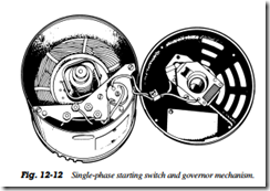
To get the split phase motor running, a run winding and a start winding are incorporated into the stator of the motor. Figure 12 12 shows the split phase motor with the end cap removed so that you can see the starting switch and governor mechanism
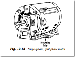
This type of motor is difficult to use with airconditioning and refrigeration equipment inasmuch as it has very little starting torque and will not be able to start a compressor since it presents a load to the motor immediately upon starting. This type of motor, however, is very useful in heating equipment (Fig. 12 13)
POLYPHASE MOTOR STARTERS
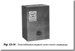
The simple manual starter works for single phase motors and also, in some instances, for polyphase motors. Most of the polyphase manual starters consisting of an on off switching arrangement are designed for motors of 1 hp or less. Figure 12 14 shows the magnetic motor starter designed for across the line control of squirrel cage motors or as primary control for wound rotor motors. They are available for nonreversing, reversing, and two speed applications. The drawing in Fig. 12 15A shows the difference between the single and three phase nonreversing type of starter. Figure 12 15B shows the reversing drawing; Fig. 12 15C is the two speed, one winding starter, and Fig. 12 15D is the two speed, two winding starter for motors up to 100 hp
During across the line starting, motor input current is five to eight times the normal full load current. This can cause an excessive temporary voltage drop on power lines that causes lights to flicker or may even interrupt the service.
 To control these temporary voltage drops, power companies have restrictions such as
• A specific maximum starting current (or kVA)
• A specific limit on kVA/hp
• A maximum horsepower motor size which can be started across-the-line
• A specific maximum line current that can be drawn in steps (increment starting)
The specified restrictions vary considerably between power companies, even within one company’s service area. It is wise to check local power company restrictions before making a larger motor installation
