Active systems such as audio amplifiers operate by drawing current from some voltage source—ideally with a fixed and unvarying output—and transforming this into a variable voltage output that can be made to perform some useful function, such as driving a loudspeaker, or some further active or passive circuit arrangement. For most active systems, the ideal supply voltage would be one having similar characteristics to a large lead-acid battery: a constant voltage, zero voltage ripple, and a virtually unlimited ability to supply current on demand. In reality, considerations of weight, bulk, and cost would rule out any such Utopian solution and the power supply arrangements will be chosen, with cost in mind, to match the requirements of the system they are intended to feed. However, because the characteristics of the power supply used with an audio amplifier have a considerable influence on the performance of the amplifier, this aspect of the system is one that cannot be ignored.
High Power Systems
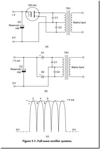
In the early days of valve-operated audio systems, virtually all of the mains-powered DC power supply arrangements were of the form shown in Figure 5.1(a), and the only real choice open to the designers was whether they used a directly heated rectifier, such as a 5U4, or an indirectly heated one, such as a 5V4 or a 5Z4. The indirectly heated valve offered the practical advantage that the cathode of the rectifier would heat up at roughly the same rate as that of the other valves in the amplifier so there would not be an immediate switch-on no-load voltage surge of 1.4, the normal HT supply output voltage. With a directly heated rectifier, this voltage surge would always appear in the interval between the rectifier reaching its operating temperature, which might take only a few seconds, and the 30 s or so that the rest of the valves in the system would need to come
into operation and start drawing current. Using an indirectly heated rectifier would avoid this voltage surge and would allow lower working voltage components to be used with safety in the rest of the amplifier. This would save cost. However, the directly heated rectifier would have a more efficient cathode system and would have a longer working life expectancy.
Although there are several other reasons for this, such as the greater ease of manufacture, by the use of modern techniques, of large value electrolytic capacitors, or the contemporary requirement that there shall be no audible mains hum in the amplifier output signal due to supply line AC ripple, it is apparent that the capacitance values used in the smoothing, decoupling, and reservoir capacitors in traditional valve amplifier circuits are much smaller than in contemporary systems, which operate at a lower output
voltage. The main reason for this is that the stored energy in a capacitor is defined by the relationship:
where Ec is the stored energy, in joules; C is the capacitance, in farads; and V is the applied voltage. This means that there is as much energy stored in an 8-μF capacitor, charged to 450 V, as there is in a 400-μF capacitor charged only to 64 V. Because the effectiveness of a decoupling capacitor in avoiding the transmission of supply line rubbish, or a power supply reservoir capacitor in limiting the amount of ripple present on the output of a simple transformer/rectifier type of power supply, depends on the stored charge in the capacitor, its effectiveness is very dependent on the applied voltage, as is the discomfort of the electrical shock that the user would experience if he or she inadvertently discharged such a charged capacitor through his or her body.


