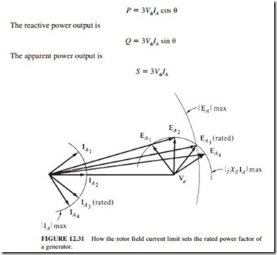
SYNCHRONOUS GENERATOR CAPABILITY CURVES
The generator capability diagram expresses the stator and rotor heat limits and any external limits on the generator. The capability diagram illustrates the complex power S P jQ. It is derived from the generator’s phasor diagram, assuming that Vcp is constant at the generator’s rated voltage.
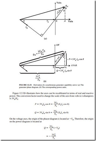
Figure 12.32 illustrates the phasor diagram of a synchronous generator operating at its rated voltage and lagging power factor. The orthogonal axis is drawn with units of volts. The length of the vertical segment AB is XS IA cos e, and horizontal segment OA is XS IA sin
The length that corresponds to XSIA on the power diagram is 3VcpIA.
Figure 12.33 illustrates the final capability curve of a synchronous generator. It illustrates
a plot of real power P versus reactive power Q. The lines representing constant armature cur- rent IA are shown as lines of constant apparent power S 3VcpIA, which are represented by concentric circles around the origin. The lines representing constant field current correspond to lines of constant EA. These are illustrated by circles of magnitude 3EAVcp/XS centered at
The armature current limit is illustrated by the circle corresponding to the rated IA or MVA. The field current limit is illustrated by the circle corresponding to the rated IF or EA.
Any point located within both circles is a safe operating point for the generator. Additional constraints such as the maximum prime mover power can also be shown on the diagram (Fig. 12.34).

