Objectives
After studying this unit, the student will be able to:
• Describe the purpose of starting motors in sequence
• Read and interpret sequence control diagrams
• Make the proper connections to operate motors in sequence
• Troubleshoot sequence motor control circuits
Sequence control is the method by which start ers are connected so that one cannot be started un til the other is energized. This type of control is required whenever the auxiliary equipment asso ciated with a machine, such as high-pressure lubricating and hydraulic pumps, must be operating before the machine itself can be operated safely. Another application of sequence control is in main or subassembly line conveyors.
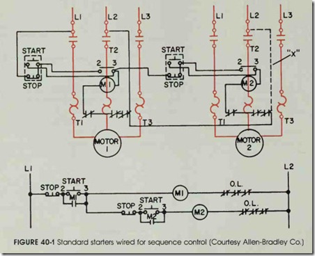
The proper push-button station connections for sequence control are shown in figure 40-1. Note that the control circuit of the second starter is wired through the maintaining contacts of the first starter. As a result, the second starter is pre vented from starting until after the first starter is energized. If standard starters are used, the con nection wire (X) must be removed from one of the starters.
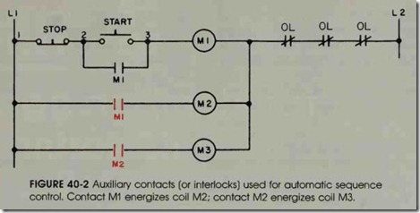
If sequence control is to be provided for a se ries of motors, the control circuits of the addi tional starters can be connected in the manner shown in figure 40-2. That is, M3 will be connected to M2 in the same step arrangement by which M2 is connected to Ml.
The stop button or an overload on any motor will stop all motors with this method.
AUTOMATIC SEQUENCE CONTROL
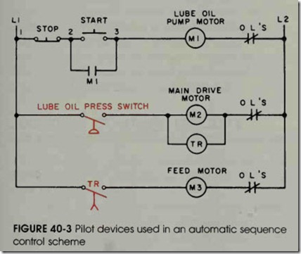
A series of motors can be started automati cally with only one start-stop control station as shown in figures 40-2 and 40-3. When the lube oil pump, (Ml) in figure 40-3, is started by pressing the start button, the pressure must be built up enough to close the pressure switch before the main drive motor (M2) will start. The pressure switch also energizes a timing relay (TR). After a preset time delay, the contact (TR) will close and energize the feed motor starter coil (M3).
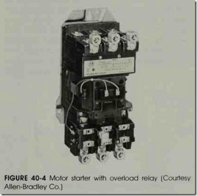
If the main drive motor (M2) becomes over loaded, the starter and timing relay (TR) will open. As a result, the feed motor circuit (M3) will be de-energized due to the opening of the contact (TR). If the lube oil pump motor (Ml) becomes overloaded, all of the motors will stop. Practically any desired overload control arrangement is pos sible. A motor starter with an overload relay is shown in figure 40-4.
REVIEW QUESTIONS
1. Describe what is meant by sequence control.
2. Referring to the diagram in figure 40-2, explain what will happen if the motor on the coil (Ml) becomes overloaded.
3. In figure 40-2, what will happen if there is an overload on the motor starter (M2)?
4. What is the sequence of operation in figure 40-2?
5. Redraw figure 40-3 so that if the feed motor (M3) is tripped out because of overload, it will also stop the main drive motor (M2).


