When the stator is energized, the synchronous motor starts like an induction motor. The amortisseur winding (like a squirrel cage winding) forms poles that react to the rotating magnetic field of the stator.
The amortisseur winding isn’t designed for long-term use (as is the case with the induction motor’s squirrel cage winding). It gives the motor adequate torque to start a minimal load. A control energizes the rotor’s DC field when the rotor reaches 95 to 98 percent of synchronous speed. The energized DC field quickly pulls the rotor up to synchronous speed. The motor is now ready for loading.
During startup, the lines of force from the stator’s rotating magnetic field cut the DC field coils’ conductors. At this time, the stator becomes the primary and the DC field becomes the secondary of an extremely highvoltage transformer. The stator coils have very high volts per turn, and very few turns. The DC field coils contain a large number of turns. When transformer theory is applied to this combination, the result is extremely high voltage in the DC field. The DC field coils are connected in series, so the voltage value of each coil adds to the next, resulting in very destructive high voltage at the slip rings.
A discharge resistor is connected across the DC field during startup (to lower the transformed high voltage). The discharge resistor affects the DC field in the same way that an overload affects a transformer. (When a transformer is overloaded, the secondary voltage drops.) The discharge resistor overloads the DC field’s transformed voltage, keeping it at a safe value.
For an instant (when the control applies DC voltage to the DC field) DC flows through both the discharge resistor and the DC field. The discharge resistor is then disconnected.
It’s very important that the DC field always have either DC power applied to it or the discharge resistor connected across it. A destructively high voltage will develop instantly if the DC field is open. This is one of the main causes of premature insulation failure in DC field coils.
The Synchronous Motor Control
The AC side of the synchronous motor control is similar to most motor controls and doesn’t need explaining.
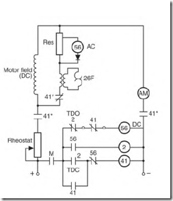
The DC side of the control is shown in Fig. 5.43. The amortisseur winding powers the rotor to 95 to 98 percent of synchronous speed (when AC is applied to the stator of the synchronous motor). As the rotor accelerates, a discharge resistor controls the voltage transformed to the DC field. An AC relay coil (no. 1) is connected across part of the discharge resistor and operates on the voltage drop across this part of the resistor.
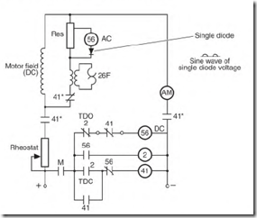
FIGURE 5.44 The single diode allows only half of the sine wave voltage to energize the control coil. The DC field and resistor are in a closed circuit during startup.
The voltage transformed to the rotor’s DC field during startup is AC. The hertz (cycles per second) of the transformed voltage varies inversely with the rotor’s RPM. (See “Amperes and Rotor Bar Design, ” earlier in the chapter.) A single diode is in series with coil 56. It will conduct only one-half of the sine wave. The half-wave pulse powers coil 56 (Fig. 5.44). As the rotor approaches 95 to 98 percent of synchronous speed (when DC should be applied), the half-wave pulses are down to about one pulse per second. The time delay between pulses is now so long that the coil can’t hold the contacts. But the voltage is always high enough to keep the coil operating. (The time lag between pulses makes the coil release the contacts.)
Three sets of contacts are activated when coil 56 drops its load (Fig.
5.45). Two sets (normally open) connect DC power to the field. The third set (normally closed) functions after the other two sets close. For an instant, the resistor and the DC field have DC power applied to them. Then a normally closed contact opens and disconnects the resistor from the circuit.
FIGURE 5.45 Current flow when motor is at full speed.
Power Factor Correction with a Synchronous Motor
The synchronous motor can be used to control the power factor of an industry’s power supply by increasing or decreasing DC field amperes.
Unlike power factor—correcting capacitors (that correct only power factor), the synchronous motor corrects the power factor and pulls a load. It operates at constant speed. A load can vary from no load to full load (while not affecting the motor’s RPM).
When no more power is applied to the DC field than it takes to pull the load, the AC power line magnetizes the iron of the AC stator. Magnetizing amperes (furnished by the power line) lower the line’s power factor. (By increasing the amperes in the DC field, the DC field provides the magnetizing amperes.) Increasing DC amperes even more creates the same effect as with a capacitor (the current leads the voltage). Magnetizing amperes (furnished by the synchronous motor’s leading current) raise the power factor of the AC supply circuit.
There are synchronous motors (with no shaft) that are used only for power factor correction. They are usually located where power factor correction is most beneficial to the building’s circuitry.
The Brushless Synchronous Motor
The brushless synchronous motor operates the same way as the brush type. The main difference is the way the DC rotor is powered. Eliminating the brushes decreases maintenance of the machine.
The brushless synchronous motor has an AC alternator (or exciter) built into its frame. Instead of brushes carrying power to the DC rotor field, an AC alternator (exciter) furnishes the DC power. The exciter’s stator field is DC and is controlled electronically by an external controller (sometimes called the black box). The black box controls the exciter and the output of the rotor components.
The receiver coils on the rotor cut the magnetic lines of force of the exciter’s stator field. The power produced by the receiver coil is AC. A rectifier is mounted on the rotor shaft with the receiver coil. Control of the discharge resistor (also mounted on the motor’s shaft) and the DC field is achieved with electronic components mounted on the rotor.
Three-Phase Alternator
The synchronous three-phase motor can be used as a three-phase alternator. The motor is rotated by a power source (diesel, turbine, or an electric motor), and DC is applied to the rotor’s DC field. The DC field’s flux cuts the stator windings and produces three-phase power.
The voltage (taken from the stator leads) can be varied by adjusting the amperes in the DC field.
Hertz is controlled by the speed of the rotor. If the alternator’s power is added to an existing power source, the voltage polarity value and hertz must match those of the existing power source.
The amortisseur (squirrel cage) winding in the three-phase alternator has a dampening effect on speed change (hunting) in the machine when it is lightly loaded.
Wound Rotor Motor
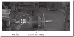
The wound rotor motor is a variable-speed induction motor (Fig. 5.46). It was one of the first variable-speed three-phase motors to be developed. Sizes range from fractional to thousands of horsepower.


