Dynamic Braking
Dynamic braking can be used to slow both direct and alternating current motors. Dynamic braking is sometimes referred to as magnetic braking because in
both instances it employs the use of magnetic fields to slow the rotation of a motor. The advantage of dynamic braking is that there are no mechanical brake shoes to wear out. The disadvantage is that dynamic brakes cannot hold a suspended load. Although dynamic braking can be used for both direct and alternating current motors, the principles and methods used for each are very different.
Dynamic Braking for Direct Current Motors
A direct current machine can be used as either a motor or generator. When used as a motor, electrical energy is converted into mechanical energy. When used as a generator, mechanical energy is converted into electrical energy. The principle of dynamic braking for a direct current motor is to change the motor into a generator.
When a generator produces electrical power, it produces counter torque, making the armature hard to turn. The amount of counter torque produced by the generator is proportional to the armature current.
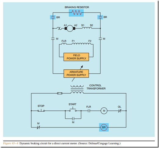
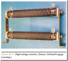
Dynamic braking for a DC motor is accomplished by permitting power to remain connected to the shunt field when the motor is stopped, and reconnecting the armature to a high wattage resistor (Figure 43 – 4). The resistor may actually be more than one resistor depending on motor size, length of braking time, and armature current. High wattage resistors are shown in Figure 43 – 5. The braking time can be controlled by adjusting the resistance value. If current remains connected to the shunt field, the pole pieces retain their magnetism. Connecting a resistance across the armature terminals causes the motor to become a generator.
Dynamic braking for a DC motor is very effective, but the braking effect becomes weaker as the armature slows down. Counter torque in a generator is proportional to the magnetic field strength of the pole pieces and armature. Although the flux density of the pole pieces will remain constant as long as shunt field cur- rent is constant, the armature magnetic field is proportional to armature current. Armature current is proportional to the amount of induced voltage and the resistance of the connected load. There are three factors that determine induced voltage:
• Strength of magnetic field. (In this instance, the flux density of the pole pieces.)
• Length of conductor. (Also stated as number of turns of wire. In this instance, it is the number of turns of wire in the armature winding.)
• Speed of the cutting action. (Armature speed)
As the armature slows, less voltage is induced in the armature windings, causing a decrease of armature current.
Dynamic Braking for Alternating Current Motors
Dynamic braking for alternating current motors is accomplished in a different way than that described for direct current motors. Dynamic braking for an AC motor can be accomplished by connecting direct current to the stator winding. This causes the stator magnetic field to maintain a constant polarity instead of reversing polarity each time the current changes direction. As the rotor of a squirrel cage motor spins through the stationary magnetic field, a current is induced into the rotor bars. The current flow in the rotor causes a magnetic field to form around the rotor bars. The rotor magnetic field is attracted to the stator field, causing the rotor to slow down. The amount of braking force is proportional to the magnetic field strength of the stator field and the rotor field. The braking force can be con- trolled by the amount of direct current supplied to the stator.
When direct current is applied to the stator winding, there is no inductive reactance to limit stator cur- rent. The only current-limiting effect is the wire resistance of the stator winding. Dynamic braking circuits for alternating current motors generally include a step- down transformer to lower the voltage to the rectifier and often include a series resistor to control the current applied to the stator winding (Figure 43 – 6).
In the circuit shown, an off-delay timer is used to determine the length of braking time for the circuit. When the START button is pushed, motor starter M energizes and closes all M load contacts to connect the motor to the line. The M auxiliary contacts change position at the same time. The normally closed M contact opens to prevent power being applied to the dynamic brake relay (DBR). The two normally open M auxiliary contacts close, sealing the circuit and supplying power to the coil of off-delay timer TR. Since TR is an off- delay timer, the TR timed contacts close immediately. The circuit will remain in this position until the STOP button is pressed. At that time, motor starter M de- energizes and disconnects the motor from the line. The normally open M auxiliary contact connected in series with timer coil TR opens, starting the timing sequence. The normally closed M auxiliary contact closes and provides a current path through the now closed TR timed contact to the coil of DBR. This causes the DBR contacts to close and connect the step-down trans- former and rectifier to the power line. Direct current is now supplied to the stator winding. Direct current will be supplied to the stator winding until the timed TR contact opens and de-energizes coil DBR.


