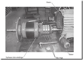
The wound rotor motor (Fig. 5.47) has a three-phase stator and frame similar to the induction motor described earlier. The stator winding is wye or delta connected (or with multiple wyes or deltas) (internally) and is usually connected one voltage.
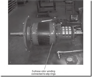
The rotor has a three-phase winding similar to the stator winding (Fig.
5.48). (The pole spacing is identical to the stator pole spacing.) The rotor winding is also wye or delta connected (or with multiple wyes or deltas). Each phase is connected to a slip ring. The rings have brushes riding on them that are connected to leads Ml, M2, and M3. These leads connect to a controller that controls the ampere flow in the rotor windings.
Operation of the Wound Rotor Motor
Three-phase voltage is transformed into the rotor winding when the stator winding is energized. This creates a three-phase voltage potential across the three slip rings. The voltage value depends on the turn ratio between the rotor winding poles and the stator poles. (Turn ratio is explained under “fransformer Function” in Chapter 3 and illustrated in Fig. 3.42.)
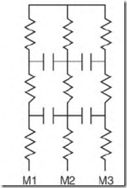
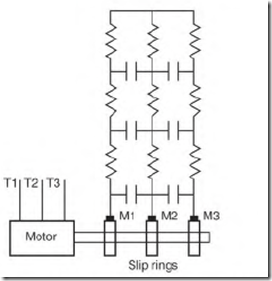
When the motor starts, the rotor control is set at its highest resistance value. The simplest explanation of the control is given in Fig. 5.49. This is a wye-connected set of resistors. (It’s very important that resistance be absolutely equal between all three phases.) Figure 5.50 shows a more
FIGURE 5.47 Stator of a wound rotor motor. Smith Services.
FIGURE 5.48 Rotor of a wound rotor motor. Smith Services.
FIGURE 5.49 Control resistors for the wound rotor motor.
FIGURE 5.50 Wound rotor motor’s control, with contacts for bypassing each resistor.
detailed control with resistors (and contacts that bypass them as more power is needed).
The control allows a low amount of current to flow in the rotor winding poles when the motor starts. The stator and rotor windings have a good phase angle (see “Phase Angle” earlier in the chapter) and good starting torque with low current. As the rotor accelerates, the controller decreases its resistance until the rotor reaches full speed. At full speed, the slip rings are shorted together, and the rotor operates as a squirrel cage rotor.
If resistance is cut out too fast, the rotor windings develop high current and high inductance. (Inductance delays the time that current flows.) When
peak magnetic power is reached in the rotor poles, the stator pole’s magnetic power has already peaked and is dropping to a lower value. The rotor pole’s peak power is now out of step with the stator pole’s peak power—a bad phase angle. The result is torque loss. The motor will still bring the load up to speed, but the result is excessive heating and needless power loss.
Even on the lowest speed setting, a wound rotor motor will accelerate to near synchronous speed if there is no load. From zero to full RPM, the control and the load regulate a rotor’s speed.
Until the motor reaches full speed (when the slip rings are shorted), the motor has low efficiency. To increase efficiency, the power (that is normally wasted as heat with resistors) can be converted to three-phase power, with a regenerative electronic control. This power is returned to the line, lowering the motor’s operating cost.


