in previous chapters, resistance, capacitance, and inductance in AC circuits were looked at individually in a circuit. In this chapter, resistance, capacitance, and inductance are observed as connected together in an AC circuit. The concepts covered in this chapter do not present any new material but apply all of the principles presented so far.
When the reactance of the inductor equals the reactance of the capacitor, it forms a resonant circuit. Resonant circuits are used in a variety of circuits in electronics.
Reactance in Series circuits
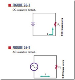
In a series circuit (Figure 26-1), the DC voltage is typi-ally supplied by a battery. The value of the amount of current flowing in a circuit may be determined by Ohm’s law, which uses the battery voltage and resistance of the circuit.
When an AC voltage source is applied to a circuit (Figure 26-2), the instantaneous value of current flowing through the resistor varies with the alternating output voltage applied. Ohm’s law applies to the AC circuit just as it does with the DC circuit. Peak current may be calculated from the source’s peak voltage, and rms current may be calculated from the rms voltage.
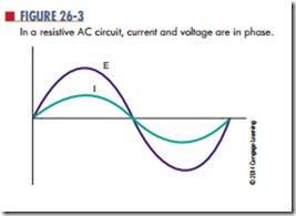
Figure 26-3 shows a graph of one cycle of AC. It shows that when the voltage reaches a peak, the
current also reaches a peak. Both the voltage and the current cross the zero line together. The two wave- forms are said to be in phase. This is the condition that occurs when a circuit contains pure resistance and no reactive components.
The effects of pure inductance or capacitance cause the voltage or current of a circuit to be 90° out of phase. This situation becomes more complex when both reactive and resistance components are combined—a condition that is typical of an AC circuit.
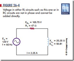
In Figure 26-4, the components are shown connected in a series circuit, and the current flows equally through both components. Resistor R1 has a value of 47 ohms, and the calculated value of inductive reactance for inductor L1 is 25.25 ohms, for the frequency of 60 hertz. The current flow in the circuit is 2.25 amperes, and the voltage drops across resistor R1 and inductor L1 are 105.75 and 56.81 volts, respectively.
These voltages appear to be incorrect because they total more than the supply voltage of 120 volts. This occurs because the voltage across the resistor is out of phase with the voltage across the inductor.
Voltage and current are in phase in the resistive portion of the circuit. In the inductive portion of the circuit, voltage leads the current by 90°. Because the current at all points in a series circuit must be in phase, ER and EL are out of phase.
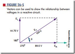
A way to represent voltage and current in circuits, such as the one in Figure 26-4, is to use vectors, arrows that start at the origin of a coordinate sys- tem and point in a particular direction (Figure 26-5). The length of the arrow indicates the magnitude: The longer the arrow, the larger the value. The angle the arrow makes with the x-axis indicates its phase in degrees. The positive x-axis is 0°, and the degrees increase as the arrow is moved in a counterclockwise direction.
In Figure 26-4, the current flows through both components with the same phase. The current vector is used as the zero-degree reference and lies on the x-axis. Voltage ER is in-phase with the current and its vector is also placed on the x-axis.
The voltage across the inductor, EL, is 90° ahead of the current. Therefore, its vector points straight up, or 90° from the x-axis. Each vector is drawn to scale. The source voltage vector 1 ET 2 is started at the origin and ends at the maximum values of ER and EL, as shown in Figure 26-5. The angle of the vector ET 1 u 2 is the phase between the source voltage and current, and its length indicates the voltage’s magnitude.
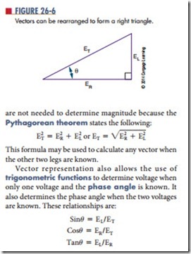
The base voltage diagram may be rearranged to form a right triangle, with the hypotenuse representing the longest vector (Figure 26-6). Scale drawings
Using the example in Figure 26-4 and any of the relationships shown, the phase difference may be determined between the supply voltage and current as 28.26°.
Experimenting with different values of EL and ER reveals several useful tips to remember:
● When a circuit is purely resistive, the phase angle is 0 because voltage and current are in phase.
● As the inductive reactance increases, the phase angle becomes greater until it reaches 45° when the resistance and the reactance are equal in value. As the inductive reactance in- creases further, the angle approaches 90°.
● When a circuit contains pure reactance with no resistance, the phase angle increases to 90°.
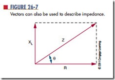
Current flow is the same through all components in a series circuit. The voltage drop across any component in the circuit is proportional to the resistance or reactance of that component. If vectors were drawn for the resistance and reactance of the circuit, they would be proportional to those drawn for the voltage (Figure 26-4). The resistance, R, would be drawn at 0° and the inductive reactance, XL, would be drawn at 90°.
The combined effect of resistance and reactance is called impedance and is represented by the symbol Z. Impedance must be used to calculate the current in a reactive circuit when the supply voltage is known. Dividing the source voltage by the resistance added to the reactance yields an incorrect answer because the voltages involved are not in phase with each other. Vectors may be used to describe the circuit impedance (Figure 26-7).
T h e s e r i e s R C circuit i n F i g u re 2 6 – 8 A i s described by the vector diagrams in Figures 26-8B and 26-8C. Again, the current is used as the zero-degree reference point, with ER at 0° because it is in-phase with the current. Remember, in a capacitive circuit, the voltage lags 90° behind the current, so its voltage vector 1 EC 2 is drawn downward. The phase angle of such a circuit is sometimes given a negative value, although it is just as acceptable to specify “leading” or “lagging” instead. All the same, trigonometric equations and the Pythagorean theo- rem may be applied to the vectors.
Questions
1. Draw a graph showing the relationship of current and voltage in a purely resistive series circuit.
2. Show the relationship between current and voltage for the circuit shown in Figure 26-9.
3. For the circuit in Figure 26-9, draw a graph showing the vector relationship. Include all arrows, and label each vector.
4. using the Pythagorean theorem, determine the impedance for the circuit shown in Figure 26-9.
5. Determine the phase angle for the circuit shown in Figure 26-9.
6. Verify the impedance for the circuit shown in Figure 26-9.
7. Verify the current flow for the circuit shown in Figure 26-9.
