Grounding motors effectively
By R. L. NAllEN, P.E.
MOST ELECTRICAL PERSONNEL are well aware of the value of a good equip ment grounding circuit. Grounding building power distribution systems is comparati ve ly easy; good guidance is available in existing codes and stan dards. However, effective grounding of rotating machinery often is not achieved because of a lack of such information or accepted practices.
If good equipment grounding of a motor or other rotating machine is to be provided, the objectives of such grounding must be fully understood . The potential between noncurrent-car rying parts of the equipment and between those parts and earth must be limited to a safe value under all condi tions of both normal and abnormal operation, and a low-impedanc e return path must be provided for ground-fault current. A high impedance would per mit dangerous voltages during a fault and could result in improper operation of protective devices. Also, high imped ance at joints and connections may cause arcing and heating of sufficient magnitude to ignite nearby combusti ble materials or explosive gases.
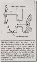
Achieving these objectives involves the installation of a grounding conduc tor or path and a proper connection at the motor. The required size of a grounding conductor may be deter mined from Sec. 250-95 of the NEC, based on the rating or setting of the automatic overcu rrent device in the circuit ah ead of the equipment. The location and method of attachment of this grounding conductor to the motor is important. A terminal mounted with two bolts is more secure than one with one bolt, sin ce rotation is prevented . However, it will take up more space, which could be a determining factor particularly on smaller motors A split-bolt connector, threaded into the motor structure, could be used for the ground connection. On the other hand, a reliable connection may require a brazed-on or welded-on grounding pad or plate to provide a raised surface and thickness for bolt-type connections on the motor frame exterior or within an enclosure or terminal box. There could be occasions when two (or more) such grounding pads are needed to pro vide for flexibility in routing grounding conductors from apparatus to selected grounding locations. Connection should be made to the largest mass of metal that is closest to the motor stator core assembly.
Very little guidance concerning mo tor grounding is available from indus try standards. The most-effective grounding specifications, techniques and components come from operating practice and experience of user and consultants, tempered by good engi neering judgm ent. The NEC, in Sec. 250-75, has this to say: Metal raceways, cable armor, cable sheath, enclosures, frames, fittings, and other met: · noncurrent-carrying parts that are to serve as grounding conduc tors shall be effectively bonded where necessary to assure electrical continuity and the capacity to conduct safely any fault current likely …Any nonconduc tive paint, enamel, or similar coating shall be removed at threads, contact points, and contact surfaces Assembly bolts are normally steel, holding together steel parts that are invariably prime-painted (if not com pletely finished) prior to assembly. Generally, these components are thought of as structural components, not as current-carrying parts. How ever, it is entirely possible that they may be called upon to carry fault cur rents. If the ground path is to be effec tive, bolted joints must have low resistance. Each joint should have its steel surfaces ground smooth and clean to obtain good electrical contact. Serrated washers used with the terminal box mounting bolts may aid in making up good joints.
NEMA Standard MG 2-1977, en titled “Safety Standard for Construc tion and Guide for Selection, Installation and Use of Electric Motors and Generators,” says, in Section MG 2.09,. . . all exposed noncurrent-carrying metal parts which are likely to become energized under abnormal conditions shall make metal-to-metal contact or otherwise be electrically connected or bonded together to provide a common ground connection.
When a motor or generator is provid ed with a grounding terminal, this ter minal shall be on a part of the machine not normally disassembled during opera tion or servicing.
DICK NAllEN, a Senior Member of the IEEE, received a B.E.E. degree with honors from the University of Santa Clara, CA. Since 1953, he has been employed in elec trical and mechanical design of rotating
apparatus up to 19,000 kVA by major motor and generator manufacturers. He is a registered P.E. in Wisconsin.
Most modern motors have few parts “not normally disassembled” during servicing. Wh ere then, should the equipment grounding connection be made? In most instances, the largest or heaviest portion of metal could be the motor end bell, the stator core assem bly, or occasionally, the frame base. Theoretically, a grounding connection made into the stator core assembly would be effective. However, this assembly is made up of the frame and core laminations. Threading a bolt into these hard silicon-steel laminations would result in a poor joint. As the stator heats and cools throughout the life of the motor, such a joint could only become less effective. On small machines, there is seldom room to make such a connection .
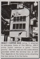
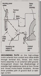
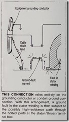
G round ing connections made to ter mi nal boxes, particularly those provid ed with large and high-voltage motors, can be a source of problems. Boxes are of various sizes and are sometimes throat-connected to the stator. Altera tions, test procedures, and mainte nance work all may affect the ground ing integrity. The result may be severe fault damage, costly downtim e, or dan ger to operating personnel. Some users install their own boxes- perhaps the original box is found to be too small. Whatever the reason, it gets reworked or replaced. When that is done, the interconnecting joints, jumpers, etc., may not be replaced properly, or there may be more bolted joints than in the original assembly. As a result, termi nal-box grounding paths may become obstructed, or high-resistance joints can be created. This is particularly true if motors are installed in wet, dirty, or corrosive surroundings. Too often, the best joint between steel parts may cor rode quickly enough to interpose high resistance in the ground path.
Line connections that carry current continuously may loosen or corrode, and the damanging results (usually overheating or “blowout”) will soon become apparent. But grounding con nections normally carry no current, and the quality of the connection has no such self-checking property.
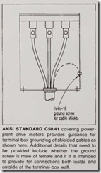
Many of these problems can be minimized by using grounding conductors extending from the closest good ground connection point via the motor supply conduit, with bonding jumpers between motor components. This may be accomplished in numerous ways, as shown in the accompanying photos and diagrams.
