SMC (SERVO MOTION CONTROL) CONTROLLERS
Servo control, which is also referred to as motion control or robotics, is used in industrial processes to move a specific load in a predetermined manner.
In practice, servo control can be used for solving two fundamental classes of motion control problems. The first general class of problems deals with command tracking, which addresses the question of how well the actual motion follows what is being commanded. The typical commands for rotary motion control are position, velocity, acceleration and torque. For linear motion, force is used instead of torque. The second general class of servo control addresses the disturbance rejection characteristics of the system. In this case, disturbances can be anything from torque disturbances on the motor shaft to incorrect motor parameter estimations. Disturbance rejection control reacts to unknown disturbances and modeling errors.
Complete servo control systems combine both these types of servo control to provide the best overall performance.
Servos are used in many applications all over the world, such as many remote-control devices, steering mechanisms in cars, wing control in airplanes, and robotic arm control in workshops. Servo control is manipulated by servo control devices, which provide all control information. A number of products have been commercially developed aimed at meeting the demands of precision servo applications, with new products currently being researched.
Servo control systems
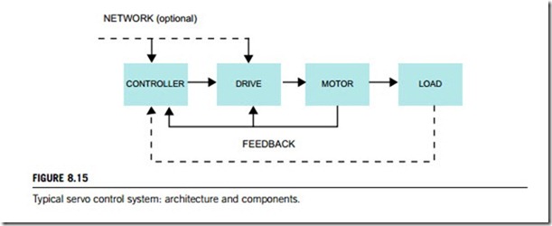
Feedback systems typical are servo control systems used to control position, velocity, and/or acceleration. Figure 8.15 is a graphical representation of a typical servo control system. The controller and industrial digital drives contain the algorithms to close the desired loop (typically position or speed) and also handle machine interfacing with inputs/outputs, terminals, etc. The drive or amplifier closes another loop (typically speed or current) and represents the electrical power converter that drives the motor according to the controller reference signals. The motor can be DC or AC, rotary or linear. It is the actual electromagnetic actuator, generating the forces or torques required to move the load. Feedback elements such as tachometers, transmitters, encoders and resolvers are mounted on the motor and/or load in order to close the various servo loops.
(1) Controller
The controller is the brains of a servo control system. It is responsible for generating the motion paths and for reacting to changes in the outside environment. Typically, the controller sends a command signal to the drive; the drive provides power to the motor; and the feedback from the motor is sent back to the controller and drive. Feedback from the load is also routed to the controller. The controller analyzes the feedback signal and sends a new signal to the amplifier to correct for errors. The controller is considered to be the intelligent part of the servo, closing the speed and/or position loops while the amplifier closes the current loop, but may also close the speed and/or position loops, placing less demand on the controller.
Controllers come in a variety of forms, selected on the basis of cost, performance, convenience, and ease of use. Most controllers fall into the category of microcontrollers, which include PIC and R/C controllers, PLCs, and motion controllers.
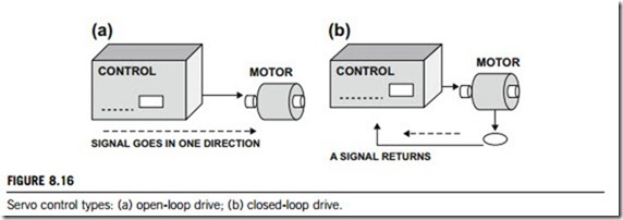
In a servo system, the controller is the device that activates motion by providing a command signal to start, or change speed, or position, or both. This command is amplified and applied to the motor, and motion commences. Systems that assume the motion has taken place (or is in the process of taking place) are termed “open loop”. An open loop drive (Figure 8.16(a)) is one in which the signal goes in only one direction from the control to the motor no signal returns from the motor or load to inform the control that action or motion has occurred.
If a signal is returned, then the system is described as having a signal that goes in two directions; the command signal goes out (to move the motor), and a signal is returned (the feedback) to the control to inform the control of what has occurred. The information flows back, or returns, and this is termed “closed loop” (Figure 8.16(b)).
The open loop approach is not good for applications with varying loads; it is possible for a stepper motor to lose steps; its energy efficiency level is low; and it has resonance areas that must be avoided. Applications that use the closed loop technique are those that require control over a variety of complex motion profiles. These may involve tight control of either speed and/or position; high resolution and accuracy; very slow, or very high velocity; and the application may demand high torques in a small package size.
(2) Drive
The servo drive is the link between the controller and motor. Also referred to as servo amplifiers, their job is to translate the low-energy reference signals from the controller into high-energy power signals to the motor. Originally, drives were simply the power stage that allowed a controller to drive a motor. They started out as single quadrant models that powered brushed motors. Later they incorporated four quadrant capabilities and the ability to power brushless motors. Four quadrants means the ability to both drive and regenerate from a motor in both directions.
Special servo drives and amplifiers are designed and manufactured for advanced motion control. They are used extensively where precise control of position and/or velocity is required. The drive or amplifier simply translates the low-energy reference signals from the controller into high-energy
signals to provide motor voltage and current. In some cases a digital drive replaces either the controller/drive or controller/amplifier control system. The reference signals represent either a motor torque or a velocity command, and can be either analog or digital in nature.
The current trend is to add more features and abilities to drives. Today drives can be expected to handle all of the system feedback including encoders, resolvers and tachometers, as well as limit switches and other sensors. Drives are also being asked to close the torque loop, speed loop and position loop and being given the responsibility of path generation. As the line between controller and drive blurs, the drive will take on many of the more complex control functions that used to be the sole domain of the controller.
(3) Motor
The motor converts the current and voltage from the drive into mechanical motion. Most motors are rotary, but linear motors are also available. Many types of motors can be used in servo applications, as discussed in subsection 8.3.4.
(4) Load
Load considerations should include the object that is being moved, the moving parts in the machine and anything that may cause unwanted instabilities, such as couplings and backlash. The total mass of the moving parts in the machine all have inertias that the motor will need to overcome. Friction points such as from linear stages and bearings will add to the motor load. Flexible couplings will add resonances that have to be considered.
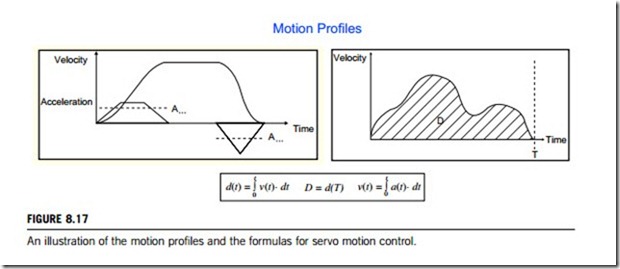
All servo systems consist of some kind of movement of a load. The method in which the load is moved is known as its motion profile. This can be as simple as a movement from point A to point B on a single axis, or as complex as bipedal stability control of a 26-axis humanoid robot. An example of a movement is shown in Figure 8.17. The y-axis represents the velocity (speed), and the x-axis represents time. The total distance travelled, D, is found by calculating the area under the curve. T is the total time required for the move. All motion profiles will require the load to accelerate and
decelerate at least once during the move. In Figure 8.17, the slope of the velocity curve represents the acceleration or deceleration at that particular instant.
There are several types of motion profiles used with servo control systems. The most often used are constant speed, trapezoidal, and S-curve motion profiles.
(5) Feedback
In modern control systems, feedback devices are used to ensure that the motor or load reaches the commanded (required) position or speed. Servo amplifiers and controllers use this feedback to determine how much current to deliver to the motor at any given time, based on its present, actual position and speed compared with that required. There are two main types of feedback; absolute and relative (also known as incremental-only).
1. Absolute feedback: absolute devices provide definitive position within a specified range without any movement (without a homing routine).
2. Relative feedback (incremental): these devices provide only incremental position updates. In order to know the motor or load’s position, this incremental feedback needs to be used in conjunction with some type of absolute feedback (a limit switch, for example).
Within these two general types of feedback, there are many different devices. Subsection 8.3.4 illustrates some of those most commonly used in motion controls.
Servo control mechanism
Servo control is the regulation of speed (velocity) and position of a motor based on a feedback signal. The most basic servo loop is the speed loop. This produces a torque command to minimize the error between speed command and speed feedback. Most servo systems require position control in addition to speed control, most commonly provided by adding a position loop in cascade or series with a speed loop. Sometimes a single PID position loop is used to provide position and speed control without an explicit velocity loop.
Servo loops have to be tuned (or compensated) for each application, by setting servo gains. Higher servo gains provide higher levels of performance, but they also move the system closer to instability. Low-pass filters are commonly used in series with the velocity loop to reduce high-frequency stability problems. Filters must be tuned at the same time as the servo loops. Some drive manufacturers deal with demanding applications by providing advanced control algorithms, which may be necessary because the mechanics of the system or the performance requirement do not allow the use of standard servo loops. In conclusion, servos are tuned or compensated through adjustments of gain and response so that the machine will produce accurate parts at a high productivity rate.
Motor control describes the process of producing actual torque in response to the torque command from the servo control loops. For brush motors, motor control is simply the control of current in motor winding, since the torque is approximately proportional to this current. Most industrial servo controllers rely on current loops, which are similar in structure to speed loops, but operate at much higher frequencies. A current loop takes a current command (usually just the output of the speed loop), compares it to a current feedback signal and generates an output that is essentially a voltage command. If the system needs more torque, the current loop responds by increasing the
voltage applied to the motor until the right amount of current is produced. Tuning current loops is always complicated work.
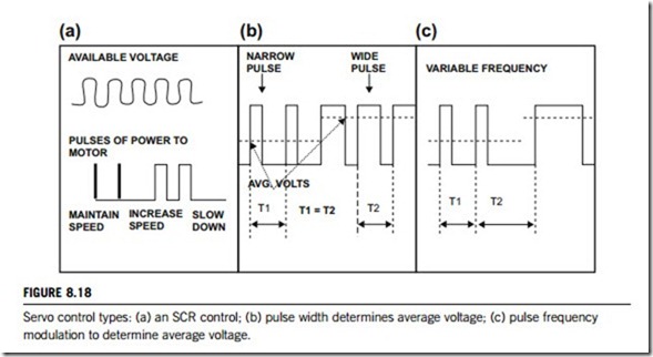
One type of semiconductor is the silicon controller rectifier (SCR), which is connected to the AC line voltage (Figure 8.18(a)). This type of device is usually employed where large amounts of power must be regulated, motor inductance is relatively high, and accuracy in speed is not critical (such as constant-speed devices for fans, blowers, conveyor belts). Power out of the SCR, which is available to run the motor, comes in discrete pulses. At low speeds, a continuous stream of narrow pulses is required to maintain speed. If an increase in speed is desired, the SCR must be turned on to apply large pulses of instant power, and when lower speeds are desired, power is removed and a gradual coasting down in speed occurs. A good example of such a system is one car is towing a second car. The driver in the first car is the SCR device and the second car, which is being towed, is the motor/ load. As long as the chain is taut, the driver in the first car is in control of the second car. But if the first car slows down slack develops in the chain and, at that point, the first car is no longer in control (and would not be until he gets into a position where the chain is taut again). So, for the periods when the first car must slow down, the driver is not in control. This sequence occurs repeatedly, resulting in a jerky, cogging operation. This type of speed control is, however, quite adequate for many applications.
If smoother speed is desired, an electronic network may be introduced. By inserting a lag network, the response of the control is slowed, so that a large instant power pulse will not suddenly be applied. The filtering action of the lag network gives the motor a sluggish response to a sudden change in load or speed command. This is not important in applications with steady loads or extremely large inertia, but for wide-range, high-performance systems, in which rapid response is important, it becomes extremely desirable to minimize this sluggishness.
Transistors may also be employed to regulate the amount of power applied to a motor. There are several techniques, or design methodologies, used to turn transistors on and off; linear, pulse width modulated (PWM) or pulse frequency modulated (PFM).
Linear mode uses transistors that are activated, or turned on, all the time, supplying the appropriate amount of power required. Transistors act like a water faucet, regulating the appropriate amount of power to drive the motor. If the transistor is turned on halfway, then half of the power goes to the motor. If the transistor is turned on fully, then all of the power goes to the motor and it operates harder and faster. Thus, for the linear type of control, power is delivered constantly, not in discrete pulses (like SCR control), and better speed stability and control is obtained.
Another technique is termed pulse width modulation (PWM), as shown in Figure 8.18(b). In this technique, power is regulated by applying pulses of variable width, that is, by changing or mod- ulating the pulse widths of the power. Compared to SCR control (which applies large pulses of power), the PWM technique applies narrow, discrete (when necessary) power pulses. Operation is as follows: for small pulse width, the average voltage applied onto the motor is low, and the motor’s speed is slow. If the width is larger, the average voltage is higher, and therefore motor speed is higher. This technique has an advantage flow power loss in the transistor, that is, the transistor is either fully on or fully off and, therefore, has reduced power dissipation. This approach allows for smaller package sizes.
The final technique used to turn transistors on and off is termed pulse frequency modulation (PFM), as shown in Figure 8.18(c). PFM, regulates power by applying pulses of variable frequency, that is, by changing or modulating the timing of the pulses. For very few pulses, the average voltage applied to the motor is low, and motor speed is slow. With many pulses, the average voltage is increased, and motor speed is higher.
Distributed servo control
There are many ways of putting together servo motion systems that combine hardware and software to meet application requirements. Some controllers operate on multiple platforms and networking buses, with units providing analog output to a conventional amplifier, as well as units that provide current control and direct pulse width modulation (PWM) output for as many as tens or even hundreds of motors simultaneously. There are amplifiers that still require potentiometers to be adjusted for the digital drives’ position, speed, and current control. A near-limitless mixing and matching of these units is possible.
Advances in hardware continue to make possible faster and note precise motion control products.
New microprocessors provide the tools necessary to create better features, functionality, and performance for lower cost. These features and functionality enhancements, such as increasing the number of axes on a motion controller or adding position controls to a drive, can be traced back to advances in the electronics involved. As dedicated servo and motion control performance has improved, the system-level requirements have increased. Machines that perform servo actions now routinely operate with more advanced software and more complex functions on their host computers. Companies that provide servo or motion systems are differentiating themselves from their competition by the quality of the operating systems they deliver to their customers.
Traditional servo systems often consist of a high-power, front-end computer that communicates to a high-power, microprocessor-based, multiple-axis motion controller card, that in turn interfaces with a number of drives or amplifiers, which often have their own high-end processors on board. In a number of these cases, the levels of communication between the high-end computer and the motion controller can be broken down into three categories: (1) simple point-to-point moves with noncritical trajectories; (2) moves requiring coordination and blending, with trajectory generation being tied to the operation of the machine; and (3) complex moves with trajectories that are critical to the process or machine.
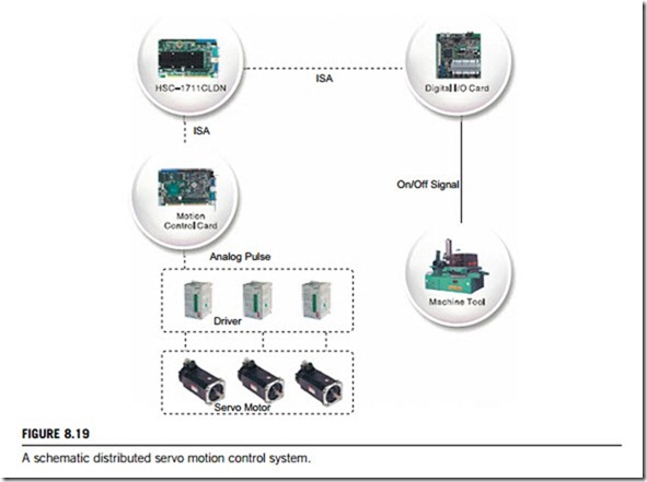
Increasingly, a significant case can be made for integrating motion control functionality into one compact module to enable mounting close to the motors, providing a distributed system. By centralizing the communications link to the computer from this controller/amplifier, system wiring would be reduced, thereby reducing cost and improving reliability. By increasing the number of power stages, the unit can drive more than one motor independently, up to the processing power of the microprocessor. If size reductions are significant enough, the distributed servo controller/ amplifier does not have to be placed inside a control panel, thus potentially reducing system costs even further. Figure 8.19 illustrates such a configuration for distributed servo control system.
To implement such a distributed servo controller and amplifier, the unit must meet the basic system requirements; it should have enough processing power to control all aspects of
a multiple-axis move, provide fast enough communications between the computer and the servo controller/amplifier to do the job, and be small enough to satisfy distributed-system requirements, and be reasonably priced.
There are two factors affecting such applications; motion control complexity and network communication requirements.
(1) Motion control complexity
The three basic levels of motion complexity require appropriate features and functions from a distributed servo controller and amplifier. Two types are possible for point-to-point moves with noncritical trajectory applications: those for repetitive point-to-point moves with external-event- generated conditions, and others for point-to-point destinations that vary based on user- or machine- generated events. A typical application for this type of system is a “pick and place” robot. The robot’s purpose can vary from moving silicon wafers between trays to placing parts from an assembly line into packing boxes.
A distributed servo controller and amplifier needs to determine a trajectory based on current location and requires either a user or a pre-programmed destination. Effectively, the user need only set acceleration, velocity, jerk parameters (for S-curve), and a series of final points.
Applications that require complex moves with critical trajectories such as inverse kinematics often include the trajectory planning as part of their own intellectual property. The generation of this trajectory is done on a computer platform and then transferred to the motion controller. Typically, significant engineering effort is put into the top-level software provided with the robot. This pre-calculates the trajectory and transfers this information to the controller, with the result that a conventional motion controller will be underused.
Meanwhile, system integration continues to advance on all fronts. All major value-adding components of motion control systems will soon have to comply with the demands for faster controllers with high-speed multiple-axis capabilities supplying commands in multitasking applications.
(2) Network communication requirements
As a unit, there are minimal communication requirements between host and controller that use simple commands and feedback. They include a resident motion program for path planning; support for I/O functionality; support for a terminal interface via such as RS-232; use without resident editor/ compiler; and stand-alone motion control. A complete motion control application is programmed into the distributed control module for stand-alone mode control of servo control applications. This mode is typically used for machines that require simple, repetitive sequences operating from such as an RS-232 terminal.
Communication for the stand-alone mode can be simple and is often not time-critical. Simple point-to-point RS-232 communication is often acceptable for applications requiring few motors. Multiple-drop RS-485 or RS-1394 is suitable for applications with many axes of motion and motor networks.
The requirements for the “blended moves with important trajectory” option involve additional communications to a host computer, as the moves involve more information, and speed and detail of feedback to the host are critical. Typical of this type a computerized numerical control system designed to cut accurate, repeatable paths. The trajectory generation and following must be smooth, as there is a permanent record of the cut. The distributed servo control module must be capable of full coordination of multiple axis control, for which communication to the host is critical. Latency times between issuing of the command and motor reaction can cause inconsistencies in the motion.
In coordinating motion between multiple motors, there are several possibilities. With a single distributed servo controller and amplifier module using multiple amplifiers, coordination can be achieved by the same controller. For applications requiring coordination between motors connected to different controllers, it is possible to achieve this with a suitable choice of high-bandwidth network.
8.3.4 Important servo control devices
This subsection introduces those devices which are important to servo control systems: servo controllers; servo motors; and feedback devices.
(1) Servo controllers
Most servo controllers are in one of three classes: speed servo controllers; position servo controllers; integrated servo controllers. Advanced servo controllers are made with both PIC (programmable integrated circuits) and R/C (radio control) technologies, so an understanding of the digital logic- circuits used is important for an understanding of how the servo controllers work.
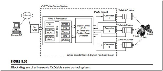
First, let us look at a classic position servo controller a three-axis XYZ-table servo controller. The servo control system for this system includes two modules: software and hardware.
The software module is a microprocessor, which has programs handling communication between the control chip and PC, process control of three-axis servo movement, and movement tracking. The hardware module is an FPGA (field-programmable gate array) which includes the
functions that control the position of three motors on the three-axis XYZ-table, a six-group programmable-interrupt controller algorithm computation, a three-group optical encoder signal- detection circuit, a three-group current-estimation circuit, a three-group vector-control coordinate conversion circuit, and a three-group space vector pulse width modulator (PWM) signal output. Figure 8.20 is the block diagram of such a system.
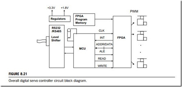
Radiocontrolled (R/C) servos have enjoyed a big comeback in recent years due to their adoption by a new generation of robotics enthusiasts. Driving these versatile servos requires the generation of a potentially large number of stable pulse width modulated (PWM) control signals, which can be a daunting task. A simple solution to this problem is to use a dedicated serial servo controller board, which handles all the details of the multichannel PWM signal generation while being controlled through simple commands issued on a standard serial UART. We will now introduce an array of 32 parallel channels (which may be extended into 64, 128, or more channels) that combines the brute force of a FPGA and the higher-level intelligence of the MCU (microprocessor control unit) to achieve some impressive specifications.
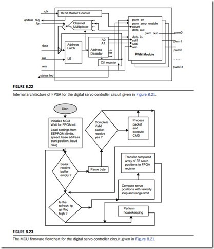
Figure 8.21 gives a block diagram of this type of digital servo controllers’ logic circuits. An array of 32 parallel channels of 16-bit accuracy, 12-bit resolution PWM generation units is implemented inside a FPGA. A MCU is used at the heart of the system. Its external memory bus interfaces with the memory-mapped array of 64 PWM registers (i.e., 32 x 16 bits) inside the FPGA. The MCU include initializes the FPGA registers with user-configurable servo startup positions stored in the internal EEPROM. In response to an external interrupt occurring at every PWM cycle, all current servo position values are refreshed in the memory-mapped PWM registers of the FPGA. This is done as a simple memory-to-memory transfer (Figures 8.22 and 8.23).
(2) Servo motors
Electric motor design is based on the placement of conductors (wires) in a magnetic field. A winding has many conductors, or turns of wire, and the contribution of each individual turn adds to the intensity
of the interaction. The force (or torque) developed from a winding is dependent on the current passing through the winding and the magnetic field strength. If more current is passed through the winding, then more force (or torque) is obtained. In effect, the interaction of two magnetic fields causes movement; the magnetic field from the rotor and the magnetic field from the stators attract each other. This is the basis of both AC and DC motor design.
(a) AC motors
AC motors are relatively constant speed devices. The speed of an AC motor is determined by the frequency of the voltage applied (and the number of magnetic poles). There are two types; induction and synchronous.
(1) Induction motor. If the induction motor is viewed as a type of transformer, it becomes easy to understand. Typically, they consist of (1) a stator with laminations and turns of copper wire and
(2) a rotor, constructed of steel laminations with large slots on the periphery, stacked together to form a “squirrel cage” rotor. By applying a voltage onto the primary (the stator) of the transformer winding, a current flow results and induces current in the secondary (rotor) winding. One magnetic field is set up in the stator, and a second is induced in the rotor. The interaction of these two magnetic fields results in motion. The speed of the magnetic field around the stator will determine the speed of the rotor. The rotor will try to follow the stator’s magnetic field, but will “slip” when a load is attached. Therefore, induction motors always rotate more slowly than the stator’s rotating field.
(2) Synchronous motor. The synchronous motor is basically the same as the induction motor but has slightly different rotor construction, which enables this type of motor to rotate at the same speed (in synchronization) as the stator field. There are basically two types of synchronous motors: self-excited (as the induction motor) and directly excited (as with permanent magnets).
The self-excited motor (which can be called reluctance synchronous) includes a rotor with notches, or teeth, on the periphery. The number of notches corresponds to the number of poles of the stator. Often the notches or teeth are termed salient poles. These salient poles create an easy path for the magnetic flux field, thus allowing the rotor to “lock in” and run at the same speed as the rotating field. A directly excited motor (which can be called hysteresis synchronous, or AC permanent magnet synchronous) includes a rotor with a cylinder of a permanent magnet alloy. The magnetic north and south poles are effect, are the salient teeth of this design, and therefore prevent slip.
(b) DC motors
DC motor speeds can be easily varied, so they are used in applications where speed control, servo control, and/or positioning is needed. The stator field is produced by either a field winding or by permanent magnets. This is a stationary field (as opposed to the AC stator field, which rotates). Passing sets up the second field, the rotor field, and current through a commutator and into the rotor assembly. The rotor field rotates in an effort to align itself with the stator field, but at the appropriate time (due to the commutator) the rotor field is switched. In this method then, the rotor field never catches up to the stator field. Rotational speed (i.e., how fast the rotor turns) is dependent on the strength of the rotor field. In other words, the more voltage on the motor, the faster the rotor will turn.
DC motors include shunt wound motors, series wound motors, and compound wound motors as well as such electromechanical actuators as stepper motors and the permanent magnet DC motors.
(3) Feedback devices
Servos use feedback signals for stabilization, speed, and position information, which may be supplied by a variety of devices such as an analog tachometer, a digital tachometer (optical encoder), or a resolver. Each of these devices will now be defined and the basics will be explored.
(a) Analog tachometers
Tachometers resemble miniature motors. In a tachometer, the gauge of wire is quite fine, so the current handling capability is small. It is not used as a power-delivering device; instead, the shaft is turned by some mechanical means and a voltage is developed at the terminals (a motor in reverse!). The faster the shaft is turned, the larger the magnitude of voltage developed (i.e., the amplitude of the signal is directly proportional to speed). The output voltage shows a polarity (þ or -) that is dependent on the direction of rotation.
Analog, or DC, tachometers, as they are often termed, provide directional and rotational information and so can be used to provide speed information to a meter (for visual speed readings) or to provide velocity feedback (for stabilization purposes). The DC provides the simplest, most direct way of doing this.
(b) Digital tachometers
A digital tachometer, often termed an optical encoder or simply an encoder, is a mechanical-to- electrical conversion device. The encoder’s shaft is rotated and gives an output signal, which is proportional to distance (i.e., angle) the shaft is rotated through. The output signal may be square, or sinusoidal waves, or provide an absolute position.
Thus, encoders are classified into two basic types: absolute encoders and incremental encoders. The absolute encoder provides a specific address for each shaft position through 360o. This type of encoder employs either contact (brush) or noncontact methods of sensing position. However, the incremental encoder provides either pulses or a sinusoidal output signal as it is rotated through 360o. Thus, distance data are obtained by counting this information.
(c) Resolvers
Resolvers look similar to small motors that is, one end has terminal wires, and the other end has a mounting flange and a shaft extension. Internally, a “signal” winding rotor revolves inside a fixed stator. This represents a type of transformer: when one winding is excited with a signal, through transformer action the second winding is excited. As the first winding is moved (the rotor), the output of the second winding changes (the stator). This change is directly proportional to the angle that the rotor has been moved through.
As a starting point, the simplest resolver unit has a single winding on the rotor and two windings on the stator (located 90o apart). A reference signal is applied to the primary (the rotor), and then, via transformer action, this is coupled to the secondary. The secondary output signal is a sine wave
proportional to the angle (the other winding would be a cosine wave), with one electrical cycle of output voltage produced for each 360o of mechanical rotation. These are fed into the controller. Inside the controller, a resolver to digital (R to D) converter analyzes the signal, producing an output rep- resenting the angle that the rotor has moved through, and an output proportional to speed (how fast the rotor is moving).
