OVERCURRENT PROTECTION
The function of the overcurrent protective device is to protect the motor branch-circuit conductors, control apparatus and motor branch circuit conductors, control apparatus arid motor from short circuits or grounds. The protective devices commonly used to sense and clear overcurrents are thermal magnetic circuit breakers and fuses. The short circuit device shall be capable of carrying the starting current of the motor but the device setting shall not exceed 250% of full load current with no code letter on the motor, or from 150 to 250% of full load current depending on the code letter of the motor. Where the value is not sufficient to carry the starting current, it may be increased, but shall in no case exceed 400% of the motor full-load current. The National Electrical Code requires (with few exceptions) a means to disconnect the motor and controller from the line, in addition to an over-current protective device to clear short circuit faults. The circuit breaker in Fig. 11 incorporates fault protection and disconnect in one basic device. When the overcurrent protection is provided by fuses, a disconnect switch is required. The switch and fuses are generally combined as shown in Fig. 12.
OVERLOAD PROTECTION
The effect of an overload is a rise in temperature in the motor windings. The larger the overload, the more quickly the temperature will increase to a point damaging to the insulation and lubrication of the motor. An inverse relationship, therefore, exists between current and time-the higher the current, the shorter the time before motor damage or ”burn out” can occur.
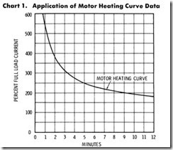
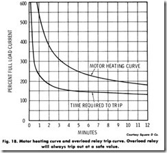
All overloads shorten motor life by deteriorating the insulation. Relatively small overloads of short duration cause little damage, but if sustained, could be just as harmful as overloads of greater magnitude. The relationship between the magnitude (percent of full load) and duration (time in minutes) of an over load is illustrated by the Motor Heating Curve shown in Chart 1.
The ideal overload protection for a motor is an element with current sensing properties very similar to the heating curve of the motor, which could act to open the motor circuit when full load current is exceeded. The operation of the protective device should be such that the motor is allowed to carry harmless overloads, but is quickly removed from the line when an overload has persisted too long.
Fuses are not designed to provide overload protection. Their basic function is to protect against short circuits. A fuse chosen on the basis of motor FLC would blow every time the motor started. On the other hand, if a fuse where chosen large enough to pass the starting or inrush current, it would not protect the motor against small, harmful overloads which might occur later.
Dual-element or time-delay fuses can provide motor overload pro tection. But, they suffer the disadvantage of being nonrenewable and must be replaced.
Overload relays consist of a current sensing unit connected in the line to the motor, plus a mechanism, actuated by the sensing unit. This unit serves to directly or indirectIy break the circuit. In a manual starter, an overload trips a mechanical latch causing the starter contacts to open and disconnect the motor from the line. In magnetic starters, an overload opens a set of contacts within the overload relay itself. These contacts are wired in series with the starter coil in the control circuit of the magnetic starter. Breaking the coil circuit causes the starter contacts to open, disconnecting the motor from the line.
There are two classifications of overload relays-thermal and magnetic. Magnetic relays react only to current excesses and are not affected by temperature. Thermal relays can be further divided into two types-melting alloy and bimetallic.
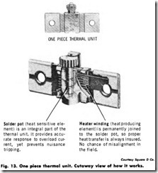
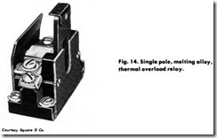
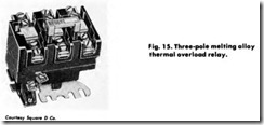
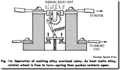
Melting alloy thermal overload relays are also referred to as solder pot relays. The motor current passes through a small heater winding. (Fig. 13). Under overload conditions the heat causes a special solder to melt. This allows a ratchet wheel to spin free. The ratchet wheel then opens the contacts. When this occurs the relay is said to “trip.” To obtain approximate tripping current for motors of different sizes, or different full load currents, a range of thermal units (heaters) is available. A reset button is usually mounted on the cover of enclosed starters. Thermal units are rated in amperes and are selected on the basis of motor full load current not horsepower. (Figs. 14, 15, and 16).
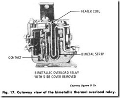
Bimetallic thermal overload relays employ a U-shape bimetal strip which is associated with a current carrying heater element. (Fig. 17).
When an overload occurs, the heat will cause the bimetal to deflect and open a contact. Different heaters give different trip points. In addition, most relays are adjustable over a range of 85% to 115% of the nominal heater rating.
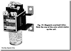
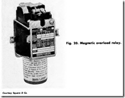
A magnetic overload relay has a movable magnetic core inside a coil which carries the motor current. The flux set up inside the coil pulls the core upwards. When the core rises far enough (determined by the current and the position of the core) it trips a set of contacts on the top of the relay. The movement of the core is slowed by a piston working in an oi 1 filled dash pot (similar to a shock absorber) mounted below the coil. This produces an inverse-time characteristic. The effective tripping current is adjusted by moving the core on a threaded rod. The tripping time is varied by uncovering oil bypass holes in the piston. Because of the time and current adjustments, the magnetic overload relay is sometimes used to protect motors having long accelerating times or unusual duty cycles. The instantaneous trip magnetic overload relay is similar but has no il filled dash pot (Figs. 19 and 20).
MANUAL STARTER
A manual starter is a motor controller whose contact mechanism is operated by a mechanical linkage from a toggle handle or push button which is in turn operated by hand. A thermal unit and direct acting overload mechanism provides motor running overload protection. Ba sically, a manual starter is an ”on-off” switch with overload relays.
Manual starters are generally used on small machine tools, fans, and blowers, pumps, compressors, and conveyors. They are the lowest cost of all motor starters, having a simple mechanism, and provide quiet operation with no ac magnet hum. Moving a handle or pushing the start button closes the contacts which remain closed until the handle is moved to off, the stop button is pushed, or the overload relay thermal unit trips.
Fractional Horsepower (FHP) Manual Starter-Fl-IP manual starters are designed to control and provide overload protection for motors of 1 hp or less on 115 or 230 volts single phase. They are available in single and two-pole versions and are operated by a toggle handle on the front.
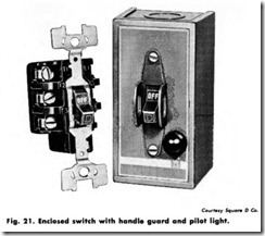
Manual Motor Starting Switches-Manual motor starting switches provide on-off control of single-phase or 3-phase ac motors where overload protection is not required or is separately provided. Two- or 3-pole switches are available with ratings up to 5 hp, 600 volts, 3-phase (Fig. 21). The continuous current rating is 30 amperes at 250 volts maximum and 20 amperes at 600 volts maximum.
The toggle operation of the manual switch is similar to the FHPstarter, and typical applications of the switch include small machine tools, pumps, fans, conveyors, and other electrical machinery which
have separate motor protection. They are particularly suited to switch nonmotor loads, such as resistance heaters.
Integral Horsepower Manual Starter-The integral horsepower manual starter is available in 2- or 3-pole versions. They are used to control single-phase motors up to 5 hp and polyphase motors up to 10 hp respectively.
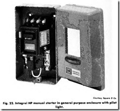
The two-pole starters have one overload relay. Three-pole starters usually have 2 overload relays but are available with 3 overload relays. When an overload relay trips, the starter mechanism unlatches, opening the contacts to stop the motor. The contacts cannot be reclosed until the starter mechanism has been reset by pressing the stop button or moving the handle to the reset position, after allowing time for the thermal unit to cool (Fig. 22).
![Fig.-11.-Circuit-breaker-overcurrent[1] Fig.-11.-Circuit-breaker-overcurrent[1]](http://machineryequipmentonline.com/electric-equipment/wp-content/uploads/2020/06/Fig.-11.-Circuit-breaker-overcurrent1_thumb.jpg)
![Fig.-12.-Fusible-disconnect-overcurr[2] Fig.-12.-Fusible-disconnect-overcurr[2]](http://machineryequipmentonline.com/electric-equipment/wp-content/uploads/2020/06/Fig.-12.-Fusible-disconnect-overcurr2_thumb.jpg)
