Basic Junction Transistor Circuit Configurations
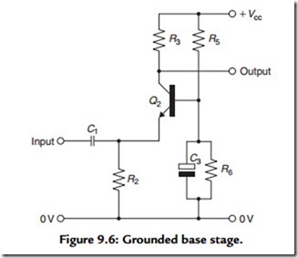
As in the case of the thermionic valve, there are a number of layouts, in addition to the simple single transistor amplifier shown in Figure 9.4 or the two-stage amplifier of Figure 9.5, that can be used to provide a voltage gain or to perform an impedance transformation function. There is, for example, the grounded base layout of Figure 9.6, which has a very low input impedance, a high output impedance, and a very good HF response. This circuit is far from being only of academic interest in the audio field in that it can provide, for example, a very effective low input impedance amplifier circuit for a moving coil pick-up cartridge. I showed a circuit of this type, dating from about 1980, in an earlier book (Audio Electronics, Newnes, 1995, p. 133).
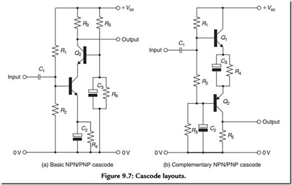
The cascode layout is also used very widely as a voltage amplifier stage, using a circuit arrangement of the kind shown in Figure 9.7(a). As in the case of the valve amplifier stage, this circuit gives very good input/output isolation and an excellent HF performance due to its freedom from capacitative feedback from output to input. It can also be rearranged, as shown in Figure 9.7(b), so that the input stage acts as an emitter–follower, which gives a very high input impedance.
The long-tailed pair layout, shown in its simplest form in Figure 9.8(a), gives a very good input/output isolation; also, because it is of its nature a push–pull layout, it gives a measure of reduction in even-order harmonic distortion. Its principal advantage, and the reason why this layout is normally used, is that it allows, if the tail resistor (R1) is returned to a –ve supply rail, both of the input signal ports to be referenced to the 0-V line—a feature that is enormously valuable in DC amplifying systems. The designer may sometimes seek to improve the performance of the circuit block by using a high impedance (active) tail in place of a simple resistor, as shown in Figure 9.8(b). This will lessen the likelihood of unwanted signal breakthrough from the –ve supply rail, as well as ensuring a greater degree of dynamic balance, and signal transfer, between the two halves.
Although like all solid-state amplifying systems it is free from the bugbears of hum and noise intrusion from the heater supply of a valve amplifying stage—likely in any valve
amplifier where there is a high impedance between cathode and ground—it is less good from the point of view of thermal noise than a similar single stage amplifier, partly because there is an additional device in the signal line and partly because the gain of a long-tailed pair layout will only be half that of a comparable single device gain stage. This arises because if a voltage increment is applied to the base of Q1, then the Q1 emitter will only rise half of that amount due to the constraint from Q2, which will also see, but in opposite phase and halved in size, the same voltage increment. This allows, as in the case of the valve phase splitter, a very close similarity, but in opposite phase, of the output currents at Q1 and Q2 collectors.

