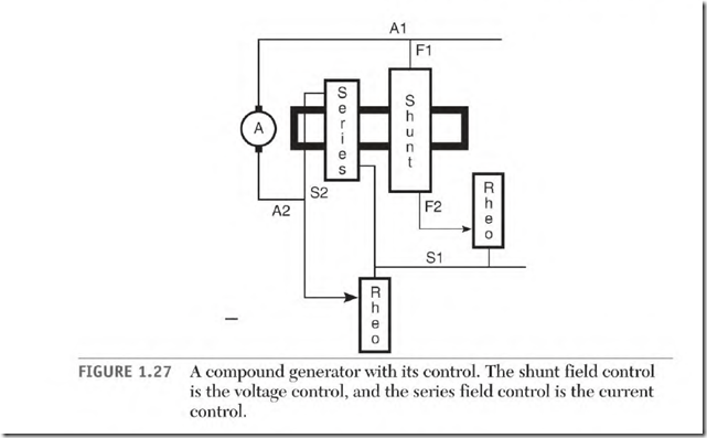
Figure 1.27 shows a (basic) compound generator control. Its two main parts are a voltage control and a current control. (The control is designed for overcompound generators and controls the voltage downward.)
The design of these controls can vary from simple variable-resistor types to electronic ones. The more sophisticated type will react quickly to load changes and produce a very stable power output.
The voltage control varies the amperes of the shunt field. (Decreasing the shunt field amperes reduces the magnetic flux and lowers the output voltage.) This control doesn’t make a large change in voltage.
The voltage control components are small compared to those of the current control because they control a small amount of current.
The current control diverts some of the amperes directly to the line ![]() bypassing the series field. (The series field raises the voltage as the load increases.) The voltage increase is controlled by diverting some amperes.
bypassing the series field. (The series field raises the voltage as the load increases.) The voltage increase is controlled by diverting some amperes.
The current control components are large because they control high amperes.
The Cumulative Compound Connection
(Generator)
The connection for the compound generator described earlier is called cumulative compound. If the series field is connected so that its polarity is the same as that of the shunt field, the connection is called cumulative. This connection adds the magnetic flux (lines of force) of the series field to that of the shunt field as the load increases. This tends to stabilize the voltage output.
The Differential Compound Connection (Generator)
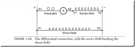
When the series field polarity is opposite that of the shunt field, the connection is called differential. This connection (Fig. 1.28) has an effect that is opposite that of the cumulative connection.
The series field flux (lines of force) will cancel an equal amount of shunt field flux. This results in fewer lines of force for the armature conductors to cut, causing the voltage output of the generator to drop. If the load is decreased, the voltage will increase.
The differential connection in a generator is used to protect a load that can be damaged by high amperes. An example is a motor that is subject to stalling or regular overloading. The connection is used on large miningequipment generators and all DC arc-welder generators.
Series Field Connections for a Motor and a Generator
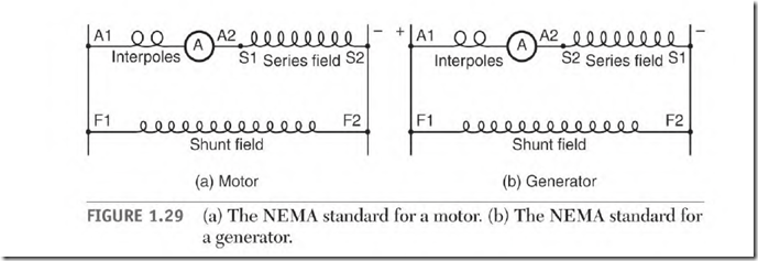
The current flow through the armature of a motor is opposite that of a generator. A motor uses amperes from the line. A generator produces amperes.
The series field leads Sl and S2 have to be reversed when a motor is used as a generator, and vice versa. Figure 1.29 shows the NEMA standard connection for both applications. If a motor connection is used on a generator, the ampere flow through the series field makes the connection differential.
Special-Purpose Machine Connections
Some special-purpose machines have an internal connection that connects the armature-interpole circuit with the series field circuit. They have one armature lead and one series field lead. Reversing these leads reverses the rotation and changes the connection from cumulative to differential.
The DC Arc Welder
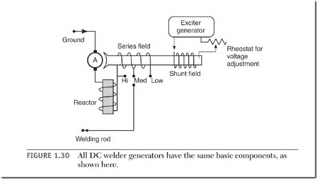
The differential connection is used in a DC arc welder (Fig. 1.30). The components of a welder include:
![]() Shunt field
Shunt field ![]() Armature and interpoles
Armature and interpoles
The exciter generator is a separate DC source for the shunt field. (It’s normally a small generator built into the machine.) It provides power for only the shunt field of the welder. Its power output is very constant and isn’t affected by the welding load.
The shunt field is located on the same pole iron as the series field. It provides a constant source of magnetic lines of force for the conductors of the armature to cut. There is no electrical connection between the two circuits.
The welding load varies from the extremely high amperes of a short to the high amperes of an arc. It is basically a controlled short. For this reason, it’s important to separately excite the shunt field so it’s not affected by the demand of the welding load.
The shunt field requires a small number of amperes, so its control components are small. The output voltage of the welder is varied just a small amount with this control.
The armature and interpole conductors must be very large. Because of the low voltage and high ampere output, there are only a few turns of wire in the slots of the armature. (They’re made of large flat wire.)
Interpole coils are connected in series with the armature. (Their coils are also made of large flat wire.) The interpole coil turns are spaced apart for maximum cooling.
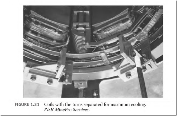
The series field coils have very large conductors. The coil turns are spaced apart for maximum cooling (Fig. 1.31).
There are usually three or more taps connected to the series field. These taps select the number of amperes as needed and are the current control
for the welder. The tap that includes all the series field turns will produce a maximum amount of canceling flux and will be the lowest ampere tap. The rest of the taps will include fewer of the series field turns. The highest ampere tap will include the least amount of series field turns.
The reactor coil consists of very large conductors. They are surrounded by iron (Fig. 1.30). The reactor’s purpose is to oppose sudden changes in current flow.
