Implementation methods
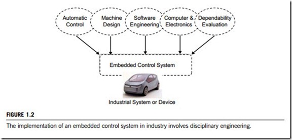
The implementation of embedded control in any industrial system or device will involve multi- disciplinary engineers, and include many types of technical projects. Figure 1.2 explains this topic, from which we learn that the completion of an embedded control system includes:
1. planning automatic control strategies;
2. verifying machine systems and components;
3. engineering of embedded software including architecture design, code programming and testing;
4. engineering of embedded hardware including computer components and electronics components;
5. carrying out dependability tests and evaluations.
Since the twentieth century, effective methodologies have been developed for implementing embedded control systems in industry. This textbook introduces two of them; control function mapping for implementing hardware of embedded control systems; and control logic modeling for implementing the software of embedded control systems.
(1) Control function mapping for hardware implementation
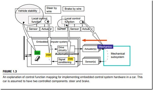
In the following explanation, the controlled system or device is considered as being divided into two subsystems or components (Figure 1.3).The method starts by providing a data map of the controlled system or device. The first data map should contain several first data map points. Each of the first data map points represents a first data map output value. Then, a function map is developed which comprises a second data map of the controlled system or device. The second data map should contain a number of second data map points. Each of the second data map points corresponds to one of the first data map points. The second data map is divided into a first-type data map region containing second data map points representing only second data map output values from the first-type, and a second-type data map region. This second-type data region contains second data map points rep- resenting second data map output values only of the second type, whereby a portion of the second data map defines a hysteresis region.
Subsequently the method determines an operating point on an operating path within the second data map in dependence upon the first and the second operating parameters of one subsystem or component of the controlled system or device. Then it determines a control function for another subsystem or component based on a first data map output value determined from the first data map and
the second data map output value determined from the second data map, in accordance with the two criteria:
(a) If the operating point in the second data map locates in a part of the first-type data map region which is outside the hysteresis region, the second data map output value should be an output from the first-type data map region. The first data map output value is interpolated from first data map output values of the first data map points adjacent to or neighboring the first data map point corresponding to the operating point in the second data map.
(b) Or, if the operating point in the second data map locates in a part of the first-type data map region which is within the hysteresis region, a check is made to deteremine whether the operating point in the second data map entered the hysteresis region from a previous operating point on the operating path within the first-type data map region. Then the second data map output value should be output from the first-type data map region and a first data map output value which is interpolated from the first data map output values of the first data map points adjacent to or neighboring the first data map point corresponding to the operating point in the second data map.
(2) Control logic modeling for software implementation
After control strategies are derived, the next task is the implementation of the hardware and software of the embedded control system. Both control theories and control strategies are topics beyond the scope of this textbook, so the following text will focus on implementing software using the control logic modeling method.
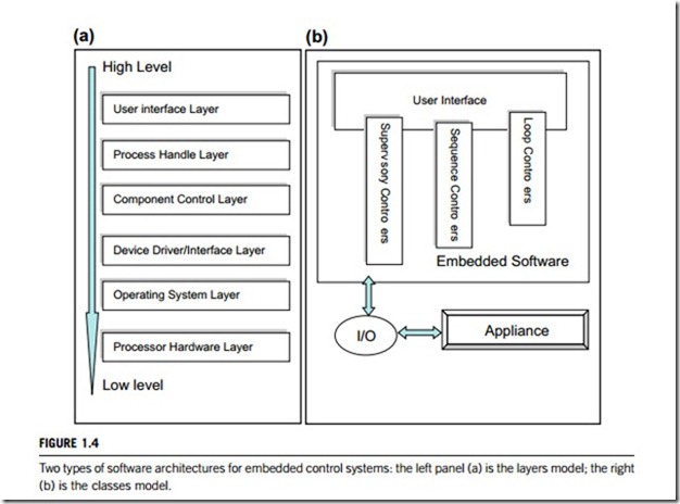
First, the software architecture for the system must be chosen. There are two types of software architectures available; the layers model and the classes model. In an embedded control system, the layers model divides the whole software organization into six layers according to the execution sequence of commands sent from the user interface. The part of the interface which first receives a command is defined as high level; the CPU located in the microprocessor chipset which finally fulfils this command is defined as low level. Please note that the layer definition here differs from the protocol for computer networks as given in the OSI (Open System Interconnect) network communication standard model. As shown in Figure 1.4(a), the six layers considered for embedded control system architecture are:
(a) User interface layer. This layer is responsible for the communication and interaction between the user and the controlled system. It receives user instructions and passes them down to a lower layer, then displays the returning results from the system to the user. This layer normally contains graphic objects such as buttons, bars, and dialog boxes, etc.
(b) Process handling layer. This layer is responsible for creating, managing and eliminating a process (also referred to as a task). It creates a process whenever it receives user instruction, then handles the running of this process, including getting parameters, managing concurrency and mutual exclusivity, etc. When a process is completed, it is deleted.
(c) Component control layer. Here, component is defined as one subsystem or individual part of the controlled system or device. For example, the scaning subsystem is one component of a copying machine; the print subsystem is another. One system or device can have several components for its control. The responsibilities of this layer include communication and interaction with the higher and lower layers, and the managing and handling of the processes running within this component.
(d) Device driver/interface layer. In this context device means a subsystem or a part of the component defined above. For example, the scanning component of a copying machine can have such a device as its paper transport driving circuit, its digital image reading circuits and the circuits that interface with other components or devices in the machine. Because it mostly consists of firmware hardcoded in programmable integrated circuits or in ASICs, this layer can be included in the operating system layer.
(e) Operating system layer. The same as a computer’s operating system software, this layer is the shell
between the microprocessor chipset and the outer components of the controlled system. It schedules processes (or tasks), manages resources such as memory and disks, and handles communication with peripherals and components.
(f) Processor hardware layer. This layer comprises the firmware of the CPU and the boot-code in the
microprocessor chipset.
In the classes model of software architecture, embedded control systems are divided into three parts; embedded software, I/O interfaces and appliances. As shown in Figure 1.4(b), the embedded software is separated from the I/O interface and appliance. The example in Figure 1.4(b) contains three controllers and the user interface. The three controllers included in embedded software are: the loop controllers which implement the control strategies, and fulfil the real-time control standards; the sequence controllers, which implement sequences of control events based on control logics, and also manage the loop controllers; and the supervisory controllers which issue expert systems optimization algorithms that adapt parameters of the lower two controllers. The user interface communicates with these controllers and interacts with users. The dynamic behaviour of the controlled system is essential for the embedded control functionality. The I/O interface chipsets, also separated from embedded software, are dedicated to the embedded control system.
After selecting the software architecture, implementation proceeds to the program design, critical for effective embedded software. The program design comprises these tasks:
(a) Splitting control strategies into the logic of the sequence controllers, the loop controllers and the supervisory controllers. The programmed objects of each of these is then designed and implement then
(b) Assigning every component or device inside the controlled system, including all the I/O interfaces, to a corresponding programmed object; filling each of these program objects with the necessary sub-objects based on the subsystems and the devices present.
(c) Incorporating external instructions from the users and the commands from connected systems into
the executing sequences of these programmed objects.
The following tools will be very useful for efficient design. The first is a data flow diagram for the software structure. In such a diagram, the vertices denote the processes and the edges denote the data communications between program objects.
The second tool is VHDL, which is an acronym for “very high-speed integrated circuits (VHSIC) hardware description language”. VHDL is used to develop ASICs and FPGAs. The third tool is a bond graph. Bond graphs are direct graphs showing the dynamic behavior of the controlled systems. Here, vertices are the sub-models, and edges denote the ideal exchange of energy. They are physical-domain independent, due to analogies between these domains on the level of physics. This has the advantage that mechanical, electrical, hydraulic, light, etc. system parts can all be modeled with the same graphs.
The next steps in implementing the embedded software are coding and testing the software. For these two topics, please refer to the Part Eight of this textbook, which provides detailed discussions on this subject.


