Not long after the cage-rotor induction motors reached industrial use, it was discovered that a small change in the number of stator or rotor slots prevented the motor to start from any rotor position or the motor became too noisy to be usable. After Georges (1896), Punga (1912), Krondl, Lund, Heller, Alger, and Jordan presented detailed theories about additional (parasitic) asynchronous torques, Dreyfus (1924) derived the conditions for the manifestation of parasitic synchronous torques.
10.9.1. When do asynchronous parasitic torques occur?
Asynchronous parasitic torques occur when a harmonic ν of the stator mmf (or its airgap flux density) produces in the rotor cage currents whose mmf harmonic has the same order ν.
The synchronous speed of these harmonics ω1ν (in electrical terms) is
ω1 (10.34)
ω1ν = ν
The stator mmf harmonics have orders like: ν =−5,+7,−11,+13,−17,+19, …, in general, 6c1 ± 1, while the stator slotting introduces harmonics of the order c N1 s ±1. The higher the harmonic order, the lower its mmf amplitude. The slip
p1
Sν of the νth harmonic is
Sν = ω1νω1− ων r =1− ν(1−S) (10.35)
For synchronism Sν = 0 and, thus, the slip for the synchronism of harmonic
ν is
S =1− ![]() (10.36) For the first mmf harmonic (ν = −5), the synchronism occurs at
(10.36) For the first mmf harmonic (ν = −5), the synchronism occurs at
For the seventh harmonic (ν = +7)
All the other mmf harmonics have their synchronism at slips
S5 > Sν > S7 (10.39)
In a first approximation, the slip synchronism for all harmonics is S ≈ 1. That is close to motor stall, only, the asynchronous parasitic torques occur.
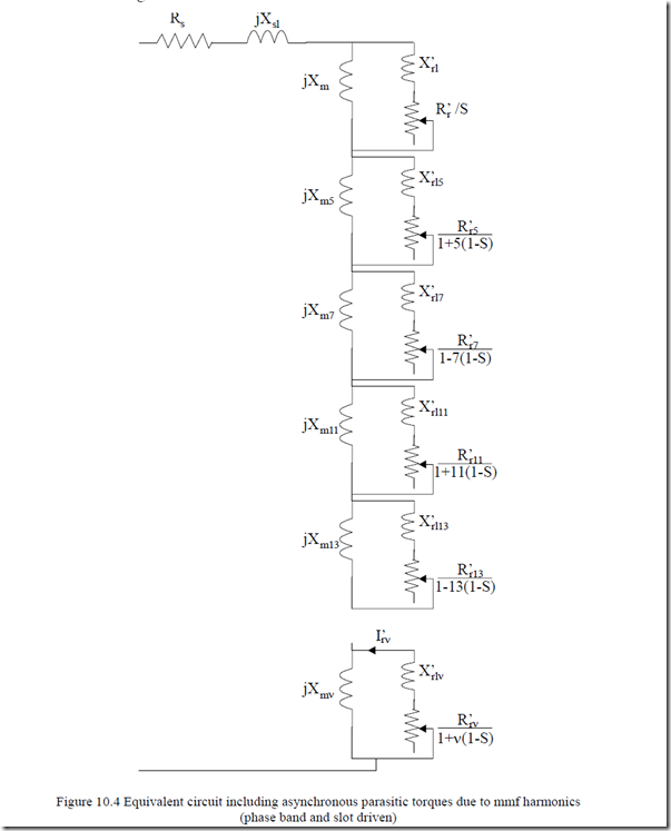
As the same stator current is at the origin of both the stator mmf fundamental and harmonics, the steady state equivalent circuit may be extended in series to include the asynchronous parasitic torques (Figure 10.4).
The mmf harmonics, whose order is lower than the first slot harmonic νsmin = Np1s ±1, are called phase belt harmonics. Their order is:−5, +7, …. They
are all indicated in Figure 10.4 and considered to be mmf harmonics.
One problem is to define the parameters in the equivalent circuit. First of all the magnetizing inductances Xm5, Xm7, … are in fact the “components” of the up to now called differential leakage inductance.
Lmν = π2p gK 11 6µ τc0( L+ Kst ) W K1ν wν 2 (10.40)
The saturation coefficient Kst in (10.40) refers to the teeth zone only as the harmonics wavelength is smaller than that of the fundamental and therefore the flux paths close within the airgap and the stator and rotor teeth/slot zone. The slip Sν ≈ 1 and thus the slip frequency for the harmonics Sνω1 ≈ ω1. Consequently, the rotor cage manifests a notable skin effect towards harmonics, much as for short-circuit conditions. Consequently, R′rν ≈ (R′r)start, L′rlν ≈
(L′rl)start.
As these harmonics act around S = 1, their torque can be calculated as in a machine with given current Is ≈ Istart.
Teν ≈ 3R’Sνrstartω1 Istart2 [(L’rl )start + LmLν2m]ν2 + R’Sνrstartω1 2 (10.41)
In (10.41), the starting current Istart has been calculated from the complete equivalent circuit where, in fact, all magnetization harmonic inductances Lmν have been lumped into Xsl = ω1Lsl as a differential inductance as if Sν = ∞. The error is not large.
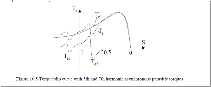
Now (10.41) reflects a torque/speed curve similar to that of the fundamental (Figure 10.5). The difference lies in the rather high current, but factor Kwν/ν is rather small and overcompensates this situation, leading to a small harmonic torque in well-designed machines.
We may dwell a little on (10.41) noticing that the inductance Lmν is of the same order (or smaller) than (L′rl)start for some harmonics. In these cases, the coupling between stator and rotor windings is small and so is the parasitic torque.
Only if (L′rl)start < Lmν a notable parasitic torque is expected. On the other hand, to reduce the first parasitic asynchronous torques Te5 or Te7, chording of stator coils is used to make Kw5 = 0.
|
qsin 56πq 2 |
5 |
Αs y/τ = 4/5 is not feasible for all values of q, the closest values are y/τ = 5/6, 7/9, 10/12, and 12/15. As can be seen for q = 5, the ratio 12/15 fulfils exactly condition (10.42). In a similar way the 7th harmonic may be cancelled instead, if so desired.
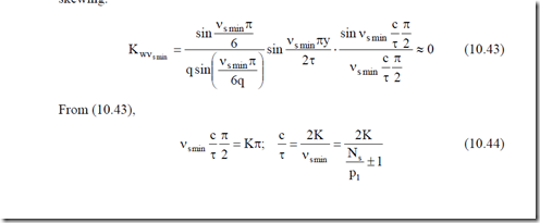
The first slot harmonics torque (νsmin = Np1s ±1) may be cancelled by using skewing.
p1
In general, the skewing c/τ corresponds to 0.5 to 2 slot pitches of the part (stator or rotor) with less slots.
For Ns = 36, p1 = 2, m = 3, q = Ns/2p1m = 36/(2⋅2⋅3) = 3: c/τ = 2/17(19) ≈ 1/9. This, in fact, means a skewing of one slot pitch as a pole has q⋅m = 3⋅3 = 9 slot pitches.
10.9.2. Synchronous parasitic torques
Synchronous torques occur through the interaction of two harmonics of the same order (one of the stator and one of the rotor) but originating from different stator harmonics. This is not the case, in general, for wound rotor whose harmonics do not adapt to stator ones, but produces about the same spectrum of harmonics for the same number of phases.
For cage-rotors, however, the situation is different. Let us first calculate the synchronous speed of harmonic ν1 of the stator.
n1ν1 = pf1ν1 1 (10.45)
The relationship between a stator harmonic ν and the rotor harmonic ν′ produced by it in the rotor is
ν − ν =’ c2 Np1r (10.46)
This is easy to accept as it suggests that the difference in the number of periods of the two harmonics is a multiple of the number of rotor slots Nr.
Now the speed of rotor harmonics ν′ produced by the stator harmonic ν with respect to rotor n2νν′ is
n 2νν‘ = p S fpν1ν1‘ = nν1‘ 1−1−νS (10.47)
With respect to stator, n1νν′ is
n1νν‘ = n + n 2νν‘ = pf11ν‘ [1+ ν − ν( ‘ 1)( −S)] (10.48)
With (10.46), Equation (10.48) becomes
n1νν’ = pf11ν’ 1+ c2 Np1r (1−S) (10.49)
Synchronous parasitic torques occur when two harmonic field speeds n1ν1 and n1νν‘ are equal to each other.
n1ν1 = n1νν‘ (10.50) or ν11 = ν1‘ 1+ c2 Np1r (1−S) (10.51)
It should be noticed that ν1 and ν′ may be either positive (forward) or negative (backward) waves. There are two cases when such torques occur.
ν = +ν1 ‘ (10.52)
ν = −ν1 ‘
When ν1 = +ν′, it is mandatory (from (10.51)) to have S = 1 or zero speed. On the other hand, when ν1 = -ν′,
( )S ν =+ν1 ‘ =1; standstill (10.53)
( )S ν =−ν1 ‘ =1+ c N22p1r <>1 (10.54)
As seen from (10.54), synchronous torques at nonzero speeds, defined by the slip ( )S ν =−ν1 ‘ , occur close to standstill as Nr >> 2p1.
Example 10.2. Synchronous torques
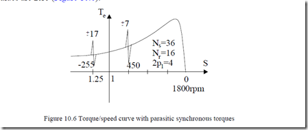
For the unusual case of a three-phase IM with Ns = 36 stator slots and Nr = 16 rotor slots, 2p1 = 4 poles, frequency f1 = 60Hz, let us calculate the speed of the first synchronous parasitic torques as a result of the interaction of phase belt and step (slot) harmonics.
Solution
First, the stator and rotor slotting-caused harmonics have the orders
ν1s = c1 Np1s +1; ν =s ‘ c2 Np1r +1; c c1 2 <> 0 (10.55)
The first stator slot harmonics ν1s occur for c1 = 1.
ν1f = +1![]() +1=19; ν1b = −1
+1=19; ν1b = −1![]() +1= −17 (10.56)
+1= −17 (10.56)
On the other hand, a harmonic in the rotor νf′ = +17 = -ν1b is obtained from (10.55) for c2 = 2.
The slip S for which the synchronous torque occurs (10.54),
S ![]() 1 rpm (10.58) Now if we consider the first (phase belt) stator mmf harmonic (6c1 ± 1), νf = +7 and νb = -5, from (10.55) we discover that for c2 = −1.
1 rpm (10.58) Now if we consider the first (phase belt) stator mmf harmonic (6c1 ± 1), νf = +7 and νb = -5, from (10.55) we discover that for c2 = −1.
So the first rotor slot harmonic interacts with the 7th order (phase belt) stator mmf harmonic to produce a synchronous torque at the slip.
These two torques occur as superposed on the torque/speed curve, as discontinuities at corresponding speeds and at any other speeds their average values are zero (Figure 10.6).
To avoid synchronous torques, the conditions (10.52) have to be avoided for harmonics orders related to the first rotor slot harmonics (at least) and stator mmf phase belt harmonics.
mmf phase belt harmonics.
|
1 2 p1 c1 = ± ±1, 2 and c2 = ± ±1, 2 For stator and rotor slot harmonics |
(10.61) |
|
c1 Ns +1≠ c2 Nr +1 |
(10.62) |
1 2 p1
c1 = ± ±1, 2 and c2 = ± ±1, 2
For stator and rotor slot harmonics
(10.61)
c1 Ns +1≠ c2 Nr +1
(10.62)
6c +1≠ c Nr +1
p1 p1
Large synchronous torque due to slot/slot harmonics may occur for c1 = c2 =
±1 when
Ns − Nr = 0; ν = ν1 2 ‘
(10.63)
Ns − Nr = 2p ; 1 ν = −ν1 2 ‘
(10.64)
When Ns = Nr, the synchronous torque occurs at zero speed and makes the motor less likely to start without hesitation from any rotor position. This situation has to be avoided in any case, so Ns ≠ Nr.
Also from (10.61), it follows that (c1, c2 > 0), for zero speed,
c N2 r ≠ 6c p1 1 (10.65)
Condition (10.64) refers to first slot harmonic synchronous torques occurring at nonzero speed:
nν =ν1 2 ‘ = pf11 (1−S)= pf11 c N22p1r = c N−22f1r (10.66)
In our case, c2 = ±1. Equation (10.66) can also be written in stator harmonic terms as
![]() nν =−ν1 2 ‘ = pf1ν1 1 = pf11 c1 Zp111 +1 = c Z1 1f1+ p1 (10.67)
nν =−ν1 2 ‘ = pf1ν1 1 = pf11 c1 Zp111 +1 = c Z1 1f1+ p1 (10.67)
with c1 = ±1.
The synchronous torque occurs at the speed nν =−ν1 2 ‘ if there is a geometrical phase shift angle γgeom between stator and rotor mmf harmonics ν1 and –ν2′, respectively. The torque should have the expression Tsν1 .
Tsν1 =(Tsν1 )max sin c Z( 1 1 + p1 )⋅ γgeom (10.68)
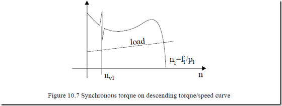
The presence of synchronous torques may cause motor locking at the respective speed. This latter event may appear more frequently with IMs with descending torque/speed curve (Design C, D), Figure 10.7.
So far we considered mmf harmonics and slot harmonics as sources of synchronous torques. However, there are other sources for them such as the airgap magnetic conductance harmonics due to slot leakage saturation.
